03/05 AWB2724-1453GB
17
2 Engineering
Control panel layout
The layout of the components inside the switchgear cabinet is a
major factor for achieving interference-free functioning of the
plant or machinery. During the project planning and design phase,
as well as its implementation, care must be taken that the power
and control sections are separated. The power section includes:
• Contactors
• Coupling/interfacing components
• Transformers
• Frequency inverters
•Converters
In order to effectively exclude any electromagnetic contamination,
it is a good idea to divide the system into sections, according to
their power and interference levels. In small switchgear cabinets it
is often enough to provided a sheet steel dividing wall, to reduce
interference factors.
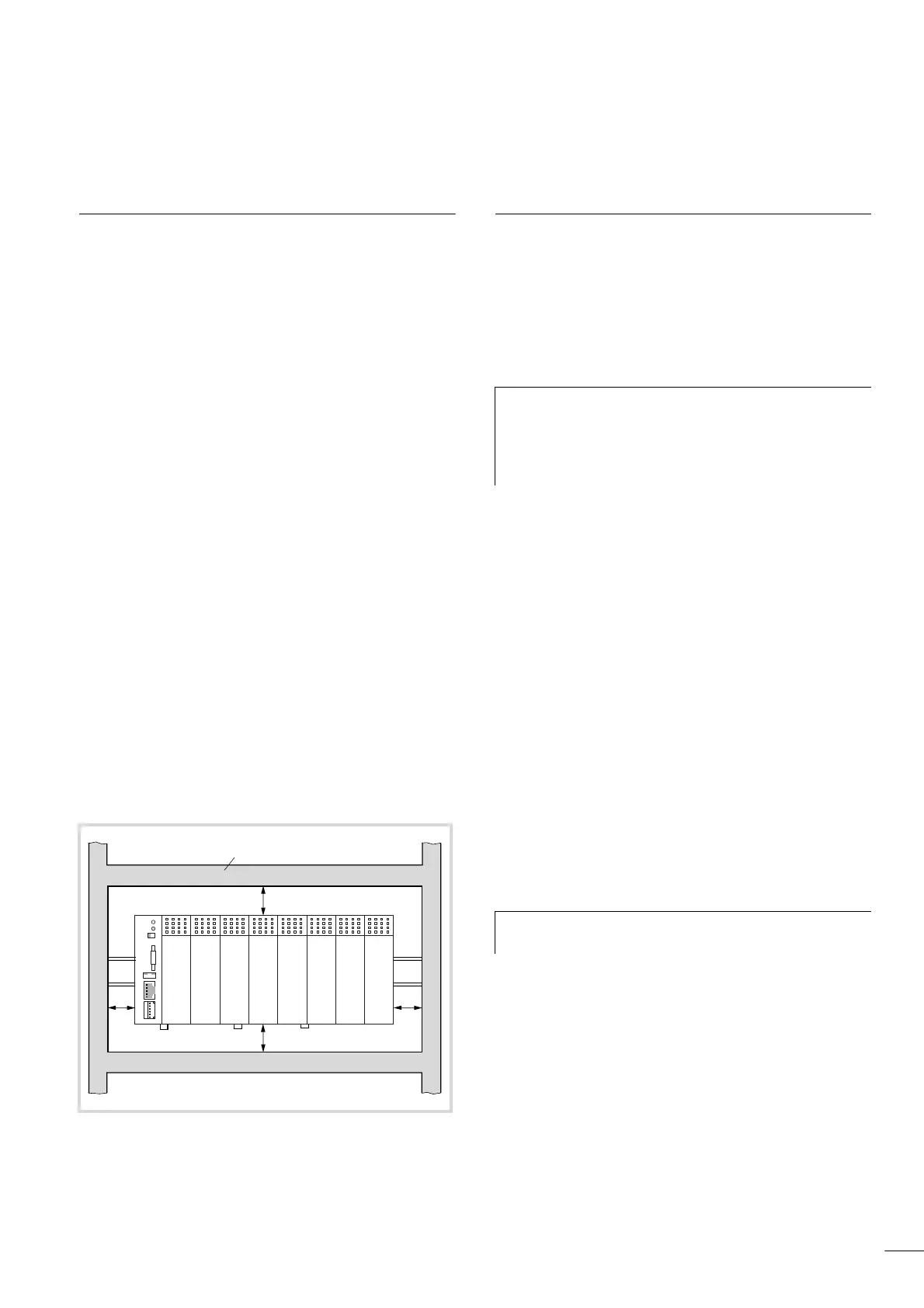
Ventilation
A clear space of at least 50 mm must be kept between passive
components, to ensure adequate ventilation. If the neighbouring
components are active elements, such as power supplies or
transformers, then the minimum spacing should be 75 mm. The
values that are given in the technical data must be observed.
Layout of units
Build the module racks and the controls into the switchgear
cabinet in a horizontal position:
Preventing interference
Cable routing and wiring
Cables are divided into the following categories:
• Power cables (e.g. cables that carry high currents, or cables to
converters, contactors, solenoids)
• Control and signal cables (e.g. for digital inputs)
• Measurement and signal cables (e.g. for fieldbus connections)
Take care to implement proper cable routing both inside and
outside the switchgear cabinet, to keep interference as low as
possible:
X Avoid parallel routing of sections of cable in different power
categories.
X As a basis rule, keep AC cable separated from DC cables.
X Keep to the following minimum spacing:
– between power cables and signal cables – at least 10 cm;
– between power cables and data or analog cables – at least
30 cm.
– When routing cables, take care that both outgoing and
return leads of a circuit pair are kept together. The currents
flowing in opposite directions thus cancel each other out as
a summation, and the electromagnetic fields cancel each
other out.
Suppressor circuitry for interference sources
X All suppressor circuitry should be wired in as close to the source
of interference (contactors, relays, solenoids) as possible.
Shielding
X Use shielded cables for the connections to the data interfaces.
The general rule is: the lower the coupling impedance, the
better the shielding effect.
Figure 17: Cabinet layout
a Spacing > 50 mm
b Spacing > 75 mm to active elements
c Cable duct
c
ba
ba
b
a
b
a
h
Always route power cables and control cable as far apart
as is feasible. This avoids capacitive and inductive
coupling. If separate routing is not possible, then the first
priority must be to shield the cable responsible for the
interference.
h
Switched inductors should always have suppressor
circuitry fitted.
 Loading...

