28
5
Trouble-shooting
Revision 3
© Moffat Ltd, September 2009
E32SUBC OVEN and PROOFER
5.4 Fault Diagnosis—Proofer
5.4.1 Fan does not operate
Relay faulty
To test refer to 3.4.6
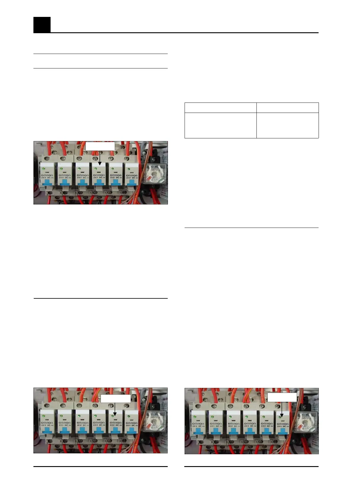
The fan & lights are controlled by relay #4
Check red flag on relay top to see if relay is ener-
gised. If no flag present check voltage (24Vdc) to
control relay coil. If voltage present replace relay.
If relay is operating check voltage through relay
contacts. Replace if no voltage through contacts
Fan motor faulty
Check the supply voltage across motor
terminals. If there is no voltage check the electri-
cal connections of supply wiring.
If voltage is correct then isolate unit from power,
then check the oven fan for free rotation.
Remove any obstruction.
If fan is free to spin and the voltage supply is
correct, then the motor is faulty—replace.
Temperature Resistance (kΩ)
0°C (32°F) 288
37°C (99°F) 56
100°C (212°F) 6.1
Element blown
With controller on and heating check voltage
across dry element terminals. If there is no
voltage check wiring. If voltage is correct,
element is faulty - replace.
To test element, disconnect terminals and check
resistance across element.
Resistances;
Proofer air heating element: 72 Ω ± 5%
5.4.3 No humidity
Humidity temperature probe faulty
To verify reading refer to 3.4.6
Water temperature probe faulty
To verify reading refer to 3.4.6
Refer to chart above for resistance readings
Relay #4
Figure 5.4.1
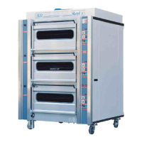
Relay #5
Figure 5.4.2
5.4.2 No dry heat
Relay faulty
To test refer to 3.4.6
The element is controlled by relay #5
Check red flag on relay top to see if relay is ener-
gised. If no flag present check voltage (24Vdc) to
control relay coil. If voltage present replace re-
lay.
If relay is operating check continuity through re-
lay contacts. Replace if no continuity through
contacts
Temperature probe faulty
To verify reading refer to 3.4.6
The temperature probe can be tested by measur-
ing the resistances across wires to diagnose the
fault is in the thermostat circuit.
Probe must be disconnected from board for test-
ing.
Relay faulty
To test refer to 3.4.6
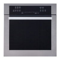
The element is controlled by relay #6
Check red flag on relay top to see if relay is ener-
gised. If no flag present check voltage (24Vdc) to
control relay coil. If voltage present replace re-
lay.
If relay is operating check continuity through re-
lay contacts. Replace if no continuity through
contacts
Relay #6
Figure 5.4.3