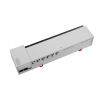
33
DEU
ENG
NDL
FRA
ITA
ESP
HZ 5 HZ 6 HZ 7 HZ 8 HZ 9 HZ 10 HZ 11 HZ 12
pump
1 2
boiler
1 2
ECO
1 2
CO
1 2
H %
1 2
HZ 1 HZ 2 HZ 3 HZ 4
1 1 1 11 12 2 2 22 2 1 1 1 11 12 2 2 22 2 1 1 1 11 12 2 2 22 2
N
N
L L TB
T4AH
System BUS
B GND24V A
HZ 5 HZ 6 HZ 7 HZ 8 HZ 9 HZ 10 HZ 11 HZ 12
pump
1 2
boiler
1 2
ECO
1 2
CO
1 2
H %
1 2
HZ 1 HZ 2 HZ 3 HZ 4
1 1 1 11 12 2 2 22 2 1 1 1 11 12 2 2 22 2 1 1 1 11 12 2 2 22 2
L1‘
TB
L2‘
L1 L2
T2A
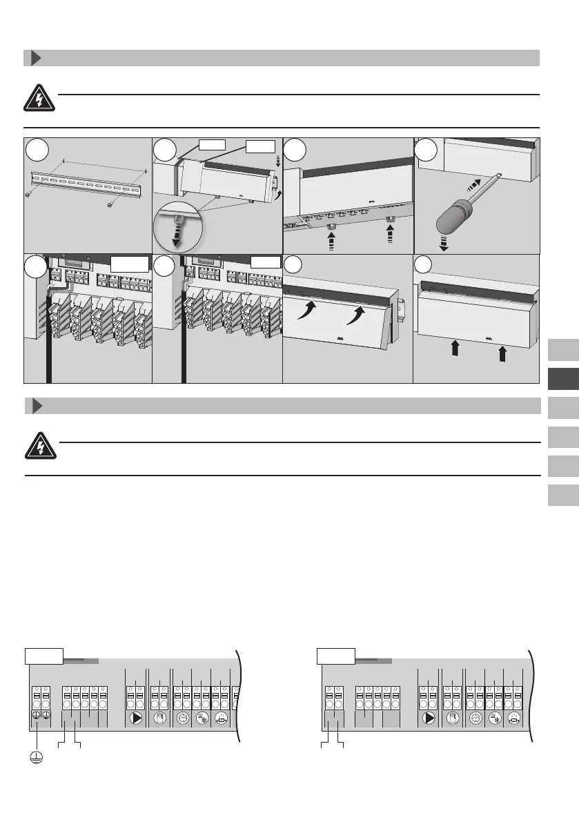
3.2 Electric connection
Warning
Electrical voltage! Danger to life!
All installation work must be performed under the absence of voltage.
The wiring of a single room control system depends on several factors and must be planned and
carried through carefully by the installer.
The following cross-sections are applicable for the plug-in/clamping connections:
9 solid wire: 0.5 – 1.5 mm²
9 fl exible wire: 1.0 – 1.5 mm²
9 8 - 9 mm insulation stripped off the wire
9 The wires of the actuators can be used with factory-mounted end sleeves.
Note: For the 230 V variant, voltage can be supplied via one of the two N and L terminal pairs.
N L L1 L2
230 V
24 V
3.1 Assembly
3 Installation
Warning
Electrical voltage! Danger to life!
All installation work must be performed under the absence of voltage.
1
2 3 4
230 V
24 V
6 7
5b
24 V
5a
230 V
electric connection,
see section 3.2
electric connection,
see section 3.2
 Loading...