36
DEU
ENG
NDL
FRA
ITA
ESP
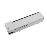
3.2.7 System BUS
HZ 5 HZ 6 HZ 7 HZ 8 HZ 9 HZ 10 HZ 11 HZ 12
pump
1 2
1 2
1 2
1 2
1 2
1 1 1 11 12 2 2 22 2 1
1 1 11 12 2 2 22 2 1 1 1 11 12 2 2 22 2
N
N
L L TB
System BUS
B GND
24V A
System BUS
B GND
24V A
System BUS
B GND
24V A
1
7
A maximum of seven base stations can be interconnected via the system BUS (syBUS) in order to
exchange global system parameters. After completing the wiring, the base stations must be paired
– see section 4.2 For a line diameter <6 mm, a strain relief must be provided by the customer.
Note! The base stations can also be connected via radio, see section 4.2. A mix of both variants is
possible.
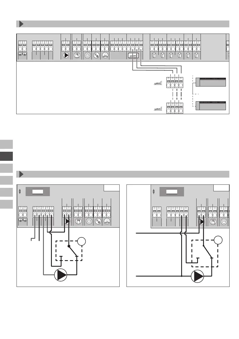
3.2.8 Use of a temperature limiter
HZ 5 HZ 6HZ 7HZ 8 HZ 9HZ 10 HZ 11 HZ 12
pump
1 2
boiler
1 2
ECO
1 2
CO
1 2
H %
1 2
HZ 1 HZ 2 HZ 3 HZ 4
111111222222 111111222222 111111222222
N
N
LLTB
T4AH
NL
1
HZ 5 HZ 6HZ 7HZ 8 HZ 9HZ 10 HZ 11 HZ 12
pump
1 2
boiler
1 2
ECO
1 2
CO
1 2
H %
1 2
HZ 1 HZ 2 HZ 3 HZ 4
111111222222 111111222222 111111222222
L1‘
TB
L2‘
L1 L2
T2A
N
L
1
230 V 24 V
Connection of a customer-supplied temperature limiter (1). This device switches off the pump and
sets the input to TL if too high flow temperatures for the floor heating are detected. If the TL input
is switched, the base station shuts down all actuators automatically.
 Loading...