35
DEU
ENG
NDL
FRA
ITA
ESP
HZ 5 HZ 6 HZ 7 HZ 8 HZ 9 HZ 10 HZ 11 HZ 12
pump
1 2
boiler
1 2
ECO
1 2
CO
1 2
H %
1 2
HZ 1 HZ 2 HZ 3 HZ 4
1 1 1 11 12 2 2 22 2 1 1 1 11 12 2 2 22 2 1 1 1 11 12 2 2 22 2
L1‘
TB
L2‘
H%
24 V~/=
0...10 V
2
1
5 4 6 3
System BUS
B GND24V A A B A B
Room BUS
rmBUS
24 V
H%
24 V~/=
0...10 V
2
1
5 4 6 3
HZ 5 HZ 6 HZ 7 HZ 8 HZ 9 HZ 10 HZ 11 HZ 12
pump
1 2
boiler
1 2
ECO
1 2
CO
1 2
H %
1 2
HZ 1 HZ 2 HZ 3 HZ 4
1 1 1 11 12 2 2 22 2
1 1 1 11 12 2 2 22 2 1 1 1 11 12 2 2 22 2
N
N
L L TB
T4AH
System BUS
B GND24V A A B A B
Room BUS
rmBUS
230 V
3.2.4 Optional humidity sensor
HZ 5 HZ 6HZ 7HZ 8 HZ 9HZ 10 HZ 11 HZ 12
pump
1 2
boiler
1 2
ECO
1 2
CO
1 2
H %
1 2
HZ 1 HZ 2 HZ 3 HZ 4
111111222222 111111222222 111111222222
N
N
LLTB
T4AH
N
L
N
L
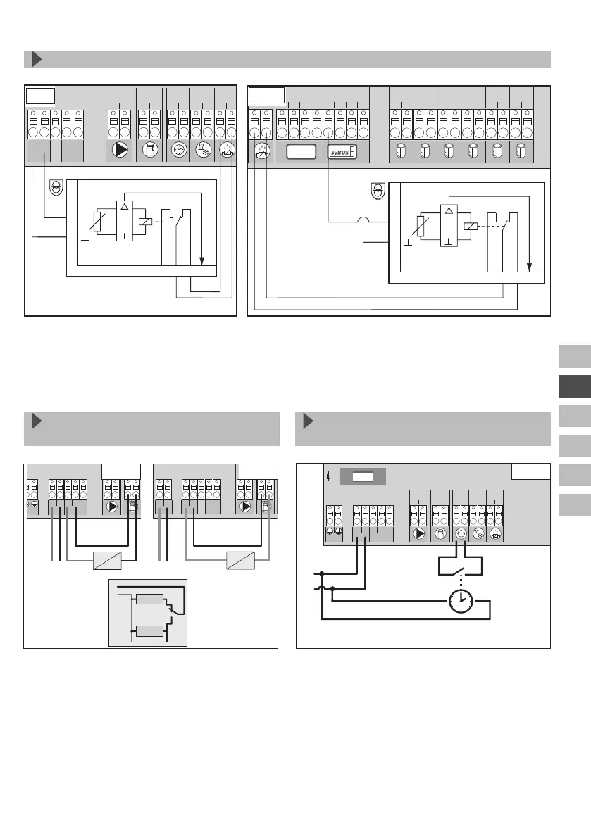
3.2.5 Pilot function for change-
over heating/cooling
3.2.6 External timer
HZ 5 HZ 6HZ 7HZ 8 HZ 9HZ 10 HZ 11 HZ 12
pump
1 2
boiler
1 2
ECO
1 2
CO
1 2
H %
1 2
HZ 1 HZ 2 HZ 3 HZ 4
111111222222 111111222222 111111222222
N
N
LLTB
T4AH
N
L
230 V
If no external change-over signal is available,
the internal pilot function of the base station
can be used for switching the overall installa-
tion between the operating modes Heating and
Cooling. A relay used by the base station for
switching over is used for this.
The base station is equipped with an ECO input
for connecting an external timer, if the internal
clock of the room control unit Radio Display
shall not be used. When the input is activated
by the timer, the heating zones are switched to
night operation.
Cooling
HZ 5 HZ 6HZ 7HZ 8 HZ 9HZ 10 HZ 11 HZ 12
pump
1 2
boiler
1 2
ECO
1 2
CO
1 2
H %
1 2
HZ 1 HZ 2 HZ 3 HZ 4
111111222222 111111222222 111111222222
L1‘
TB
L2‘
L1 L2
T2A
L1
L2
N
L
Heizen
Kühlen
HZ 5 HZ 6HZ 7HZ 8 HZ 9HZ 10 HZ 11 HZ 12
pump
1 2
boiler
1 2
ECO
1 2
CO
1 2
H %
1 2
HZ 1 HZ 2 HZ 3 HZ 4
111111222222 111111222222 111111222222
N
N
LLTB
N
L
230 V 24 V
Heating
Humidity sensors (to be provided by the customer) serve for dewing protection in the cooling
mode.
 Loading...