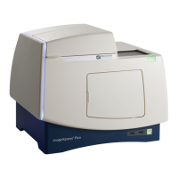
ImageXpress Pico Automated Cell Imaging System Installation Guide
32 5063666 K
Standalone Configuration
To connect cables for a standalone configuration:
1. Do the following to connect the supplied Ethernet cable:
a. Connect one end of the Ethernet cable to the LAN1 port on the instrument.
b. Connect the other end of the Ethernet cable to an Ethernet port on the host computer.
CAUTION! Do not use a wireless connection or a USB-to-Ethernet adapter to
connect the host computer to the instrument.
In a standalone configuration, where the instrument is directly connected to the host
computer, you may also want to connect the host computer to your network. In this
case, connect the host computer to the network using a second Ethernet port, a
wireless connection, or a USB-to-Ethernet adapter.
2. Do the following to connect the supplied power cord:
a. Connect the power cord to the power port on the instrument.
b. Connect the other end of the power cord to a grounded electrical wall outlet or an
uninterruptible power supply (UPS). See Power Requirements on page 26for details.
Network Configuration or Server Configuration
To connect cables for a network configuration or server configuration:
1. Do the following to connect the supplied Ethernet cable:
a. Connect one end of the Ethernet cable to the LAN2 port on the instrument.
b. Connect the other end of the Ethernet cable to a network port.
2. Do the following to connect the supplied power cord:
a. Connect the power cord to the power port on the instrument.
b. Connect the other end of the power cord to a grounded electrical wall outlet or an
uninterruptible power supply (UPS). See Power Requirements on page 26for details.
CAUTION! Do not simultaneously connect Ethernet cables to both the LAN1 port and
LAN2 port of the instrument. Doing so can degrade performance of the instrument or
cause unexpected behavior.

 Loading...