15
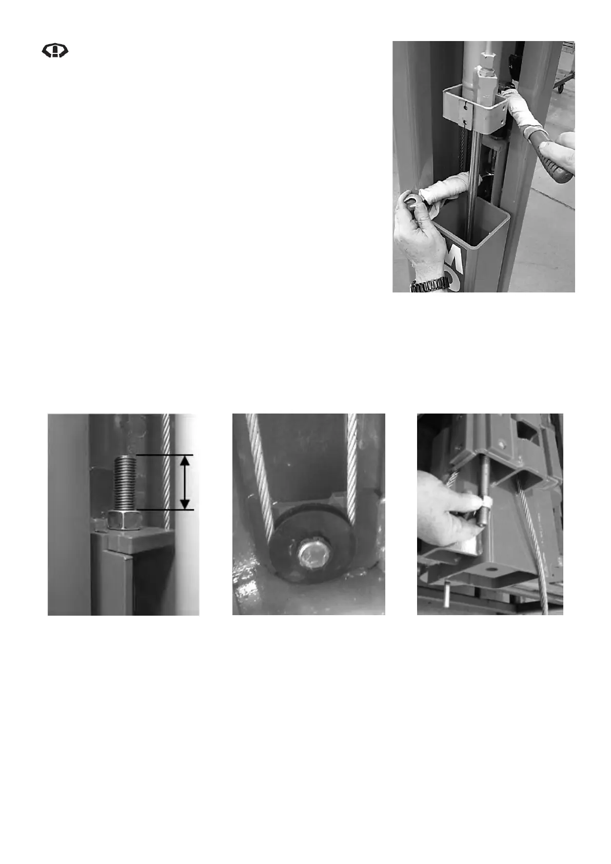
When working on the cable ends, protect the exposed
cylinder rod by thickly wrapping a soft cloth around
the tools used. If the cylinder rod is damaged it may
lead to damage of cylinder seals and cause the
cylinder to leak. Avoid contacting the cylinder where
possible. Refer to Diagram 24
1. Set hoist on first lock and hold down the release lever for 10
seconds to ensure the load is on the locks.
2. Remove all cylinder covers.
3. Measure and note the amount of thread protrusion of the
top cable end located at the top of each carriage. Refer to
Diagram 25
4. If top cable end thread protrusion is less than 40mm, go to
step 5, if greater than 40mm, follow these steps;
a. Loosen off the nut until the top of the nut is level with
the top of the top cable end thread on both sides.
b. Remove the bottom pulley from both posts and note
orientation of pulley. Refer to Diagram 26
c. Pull the bottom cable end down from the bottom of
each carriage and wind each nut on a further 25mm.
Refer to Diagram 27
d. Clean old grease from bottom pulleys and bottom pulley pins then re-grease.
e. With the cables seated in the grooves, refit the bottom pulleys on both posts ensuring the
small shoulder is facing towards the post (away from circlip) when refitting.
Diagram 25 - Top Cable End
Thread Protrusion
Diagram 26 - Bottom Pulley
Secured with Circlip
Diagram 27 - Bottom Cable End
Adjustment
5. Starting at the control post, then repeat for non-control post:
Use a 9/16” open ended spanner to hold the balance cable end inside the top of the carriage safety
rack. Use a 24mm deep socket with ratchet to loosen the cable nut till the top of the nut is just level
with the end of the cable. Avoid contacting the cylinder rod with the tools. Refer to Diagram 24
6. On all accessible sections of balance cables, clean dirt and old lubricant if necessary, inspect for
damage by ‘reverse bending’ (bending 90 degrees in opposite directions) the cables to expose any
broken wires and then lubricate with Wire Rope lubricant.
7. Inspect all balance cable pulleys (per side there are 2 top, 1 bottom) for;
a. wear in the groove, and
Diagram 24 – Cable End
Adjustment with Soft Cloth Covered
Tools to protect Cylinder