12
Rev. 1.0
4/29/2016
M2 Quick Setup Guide Manaul
Note:
Symbol Description
MCCB Circuit Breaker
NF Noise Filter
P_on Power On Switch
P_off Power Off Switch
E_stop Emergency Stop Switch
MC Magnetic Contactor
Alm_R Alarm Relay
Alarm Alarm Relay Contactor
3.2.3 Recommend Cable Specications
• For drive’s main circuit, please use wires withstands at least 600Vac.
• Please select wires with sufficient allowance for parameters such as operating current, and
ambient temperature.
• Recommended wire selections a
re as follows:
Matched Servo Drive and Motor
Wire Diameter mm
2
(AWG)
L1/L2/L3 L1C/L2C U/V/W B1+,B3
M2DV-1D82*
SM0401AE4-KCD-*NV
1.25
(AWG16)
1.25
(AWG16)
1.25
(AWG16)
2.0
(AWG14)
SM0402AE4-KCD-*NV
1.25
(AWG16)
1.25
(AWG16)
1.25
(AWG16)
2.0
(AWG14)
SM0601AE4-KCD-*NV
1.25
(AWG16)
1.25
(AWG16)
1.25
(AWG16)
2.0
(AWG14)
M2DV-3D02* SM0602AE4-KCD-*NV
2.0
(AWG14)
2.0
(AWG14)
2.0
(AWG14)
2.0
(AWG14)
M2DV-4D52* SM0803AE4-KCD-*NV
3.5
(AWG12)
3.5
(AWG12)
3.5
(AWG12)
3.5
(AWG12
)
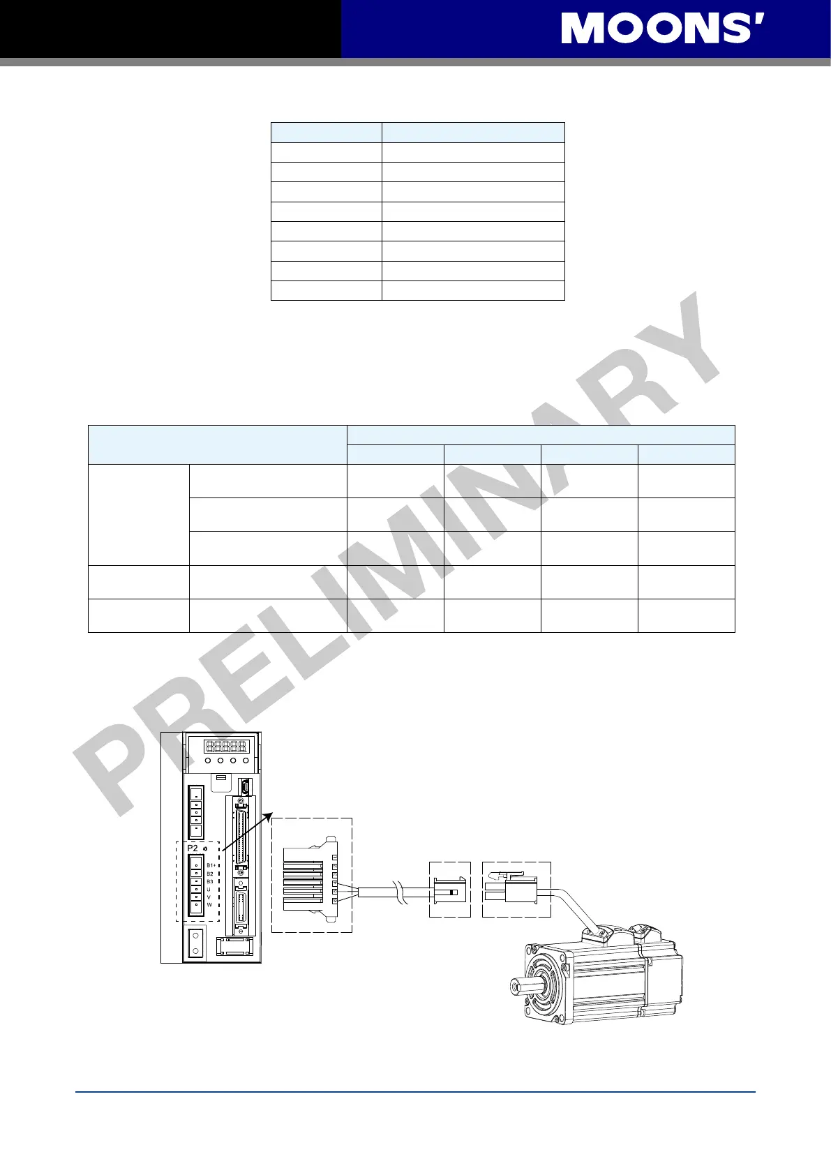
3.3 Wiring to the Connector,P2
3.3.1 Motor Power Cable Conguration
P2 connector Interface of the Drive
Motor power
extension cable connector
Lead wire
of the motor connector
NOTE: Please refer to section 3.3.2 Motor Power Cable Connector Specications for
details

 Loading...


