22
Rev. 1.0
4/29/2016
M2 Quick Setup Guide Manaul
3.8.5 Specications of Encoder Connector
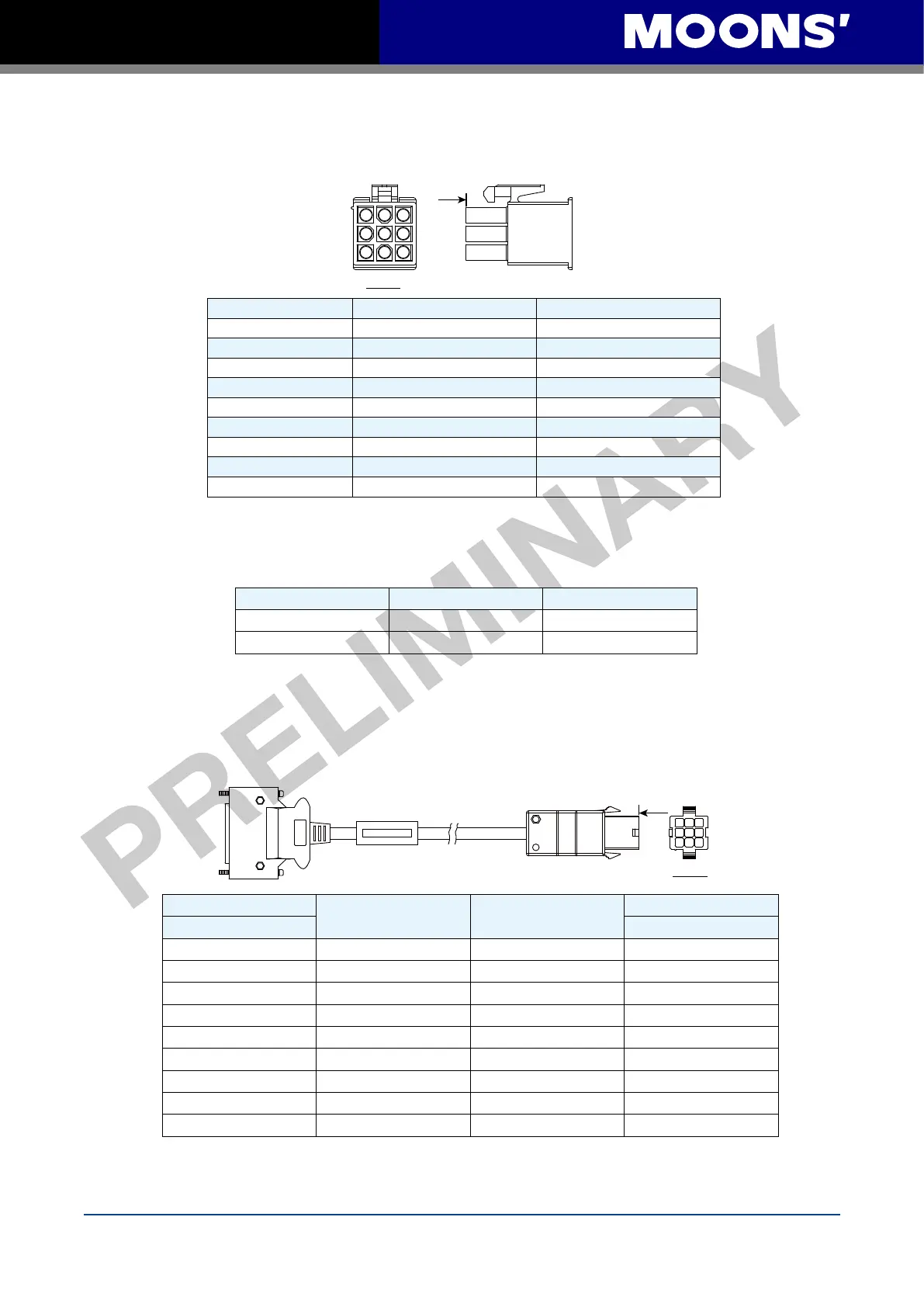
A. 9PIN AMP Connector
◆
PIN Assignment
1 3
7
9
View A
PIN#
Signal Colour
1
U+/A+ Blue
2
V+/B+ Green
3
W+/Z+ Yellow
4
U-/A- Yellow/Black
5
V-/B- Green/Black
6
W-/Z- Yellow/Black
7
+5V Red
8
GND Black
9
Shield Shield
NOTE: HALL signal U/V/W will only appear for 1.5 seconds when encoder power is applied,
and it will switch to A/B/Z signals after.
◆
Specification of 9PIN AMP Connector
Type Plug of the Motor Housing for the motor
Housing AMP 172169-1 AMP 172161-1
Crimp AMP 770835-1 AMP 770834-1
3.8.6 Wiring Diagram of Motor Encoder Extend Cable
A. Diagram of 9PIN Encoder Cable
Connect to drive
Connect to Motor
1
3
7
9
A
View A
Drive Side
Signal Colour
Housing for the motor
3M 26PIN PIN脚 AMP 172161-1
1 A+/U+ Blue 1
2 B+/V+ Green 2
3 Z+/W+ Yellow 3
14 A-/U- Yellow/Black 4
15 B-/V- Green/Black 5
16 Z-/W- Yellow/Black 6
11 +5V Red 7
24 GND Black 8
26 Shield Shield 9

 Loading...


