13
Rev. 1.0
4/29/2016
M2 Quick Setup Guide Manaul
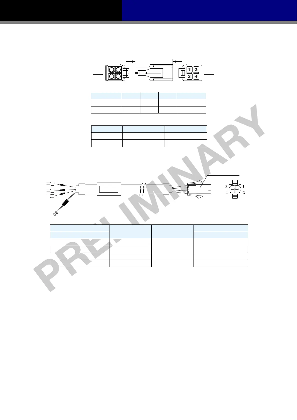
3.3.2 Motor Power Cable Connector Specications
◆ PIN Assignment
A B
View A View B
PIN 1 2 3 4
Signal U V W PE
Colour Red Yellow Blue Yellow/Green
◆ Model of Motor Connector
Type Motor Side(Plug) Plug-in(Housing)
Housing AMP 172167-1 AMP 172159-1
Crimp
AMP 170360-1 AMP 170362-1
3.3.3 Wiring Diagram of Motor extend Cable
Housing: 172159-1(AMP)
Terminal: 170362-1(AMP)
Drive Side(P2)
Signal Colour
Motor Side(Housing)
(JST) S06B-F32SK-GGXR AMP 172159-1
4 U Red 1
5 V Yellow 2
6 W Blue 3
Grounding Screw PE Yellow/Green 4
NOTE: Ensure U/V/W are following the order of RED-YELLOW-BULE. Wrong connections
will cause motor stop rotation, or wrong rotatory directions.

 Loading...


