19
Rev. 1.0
4/29/2016
M2 Quick Setup Guide Manaul
3.7.2.3 Output Signals
M2 series AC servo drive has 6 programmable digital outputs available, each of the output can be
specified with different function via parameter settings.
Signal Symbol Pin NO. Details
Y1
Y1+ 37
This output has two functions:
●
Alarm Output
●
General Output
Y1- 36
Y2
Y2+ 11
This output has two functions:
●
Motor brake control output
●
General Output
Y2- 10
Y3
Y3+ 42
●
Torque Reached Output
●
General Output
Y3- 33
Y4
Y4+ 43
●
Moving signal output, output signal when dynamic position error less
than set value in position mode.
●
Velocity reach output. Output signal when actual speed is same as the
target speed and the speed ripple less than ripple range.
●
General Output.
Y4- 33
Y5
Y5+ 40
●
Servo ready output. Output servo ready signal when the drive is ready
to be controlled and without alarm.
●
General Output.
Y5- 41
Y6
Y6+ 14
●
In position signal output, output signal when in position, and the
position error less than set value in position mode.
●
Tach out output. Tach output, produces pulses relative to the motor
position with configurable resolution.
●
General Output.
Y6- 13
Encoder pulse
feedback Output
AOUT+ 21
The encoder feedback phase A line drive output.
AOUT- 22
BOUT+ 48
The encoder feedback phase B line drive output.
BOUT- 49
ZOUT+ 23
The encoder feedback phase Z line drive output.
ZOUT- 24
ZOUT 19
The encoder feedback phase Z output.(Open collector)
+10V
Output
+10V Us
er 20
+10Vdc user ,max 100mA
USER_GND 25
+10Vdc user Ground
3.7.3 Encoder Feedback Ouput
M2 series AC servo drive can output encoder A/B/Z phase as differential output signals through
line driver. The output signal is 5V, A/B signals are 10000 pulse/rev, Z signal is 1pluse/rev.
The host must use line receiver to receive the signals. Please use twist pair wires for signal
transfers.
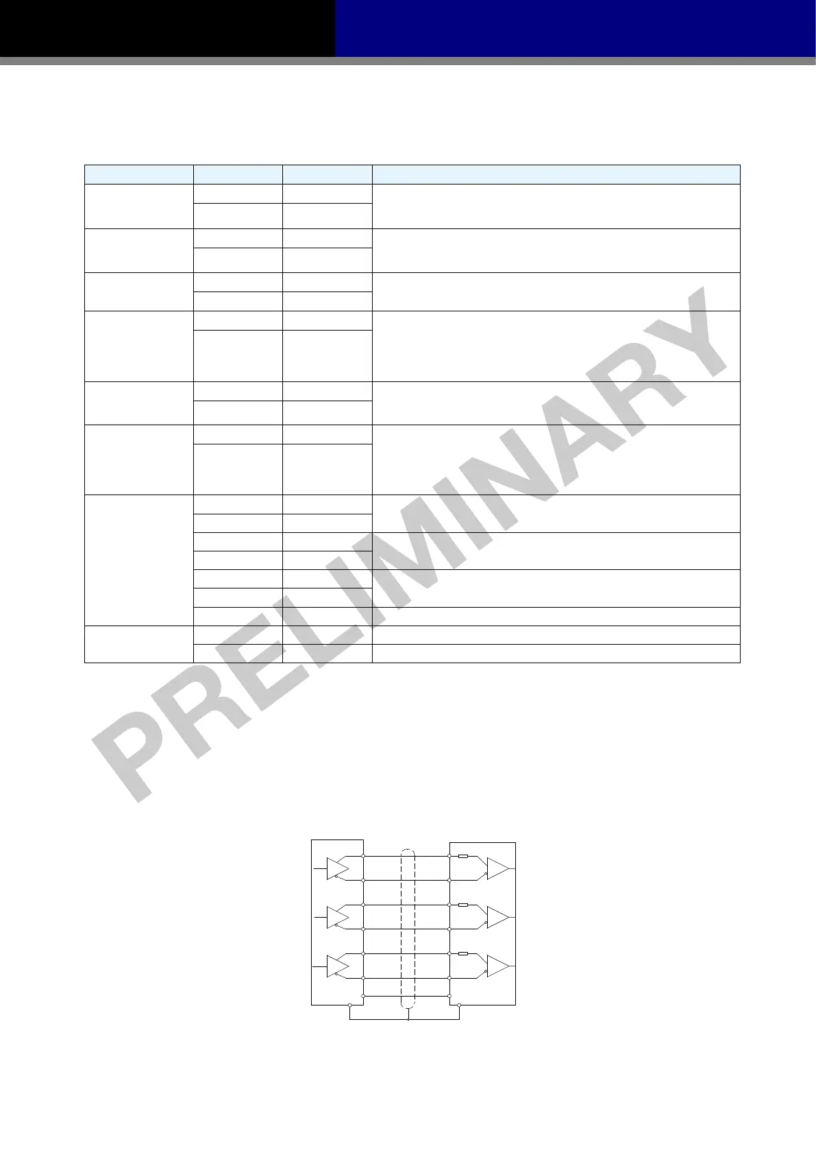
3.7.3.1 A/B/Z Wiring Method
Host Controller
A+
Servo Drive
A-
B+
B-
Z+
Z-
AOUT+
AOUT-
BOUT+
BOUT-
ZOUT+
ZOUT-
FG FG
21
22
48
49
23
24
DGND
25
50
DGND
NOTE:Please make sure the host controller and the servo drive have a same ground.

 Loading...


