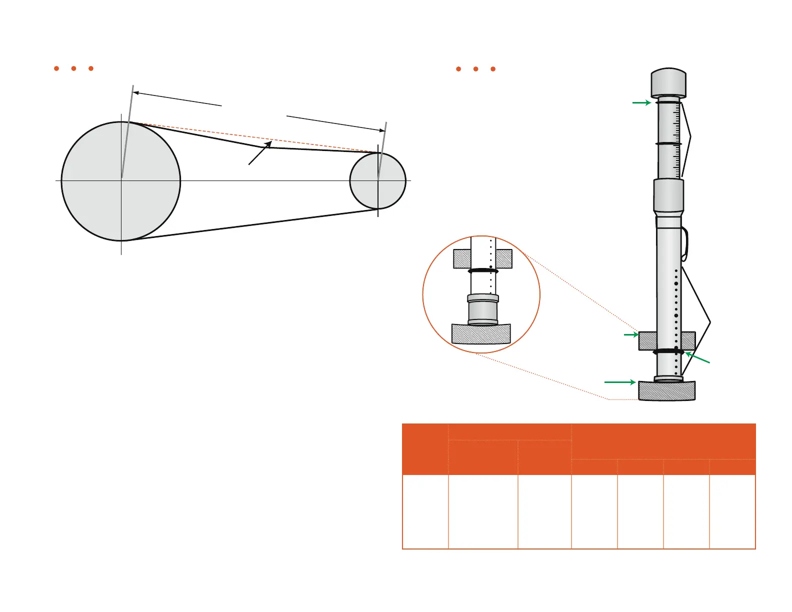
Belt Span
Straight
edge or belt
2. Measure the belt span length of the drive, and lay a straight edge across
the drive (see Figure 4.4).
3. Set the large rubber O-ring on the body of the tension gauge at the
dimension equal to span length (See inset in Figure 4.5).
4. Set the small O-ring on the plunger to “0” against the body of the tension
gauge (see Figure 4.5).
5. With the tension gauge perpendicular to the span, apply force to the belt
in the center of the span. Deflect the belt until the bottom of the large O-
ring is even with the bottom of the straightedge laid across the top of the
drive. Release the pressure and read the pounds of force used at the O-
ring on the plunger (See inset in Figure 4.5).
6. Compare the result with the ranges in Table 4.4. The proper tension is the
lowest tension at which the belts won’t slip under peak load conditions.
7. Tighten the engine adjustment bolts until the belt tension is in the
recommended range. Put the belt guard on.
NOTE: Adjust both sides evenly to ensure proper sheave alignment.
NOTE: Tension on newly installed belts drops rapidly during the first hours of
operation. Check and adjust frequently during the first 24 hours. It is
recommended the tensioning deflection force should fall between the
minimum and maximum values shown Table 4.4.
Figure 4.4
Figure 4.5
50
100 150
Pounds
302520
15105
Small
0’ ring
Large
0’ ring
Deflection
Force
Scale
Span
Scale
Belt
Straight
Edge or
Belt
Table 4.4 • Recommended Belt Tension
V-belt-
Section
Small Sheave Deection force in lbs. for Drive Speed
Ratio of;
Speed Range
Diameter 1.0 1.5 2.0 4.0+
5VX 1200 - 3600
1200 - 3600
1200 - 3600
1200 - 3600
900 - 1800
900 - 1800
4.4
5.2
6.3
7.1
9.0
14.0
6.5
8.0
9.5
10.0
12.0
14.0
7.5
9.0
10.0
11.0
13.0
15.0
8.0
9.5
11.0
12.0
14.0
16.0
9.0
10.0
12.0
13.0
15.0
17.0
General Maintenance • Belt Tension
50
inches of
76347-385 • 06 -15
4.9