ʅʩʓʳɮᚽᏚᴥɴʡʁʱʽᴦ
SEMI DRY-CUT SYSTEM (OPTION)
140
15 ʅʩʓʳɮᚽᏚᴥɴʡʁʱʽᴦ
SEMI DRY-CUT SYSTEM (OPTION)
15-1 บΖፈᦀɁᝩ
Adjusting Oil Supply Quantity
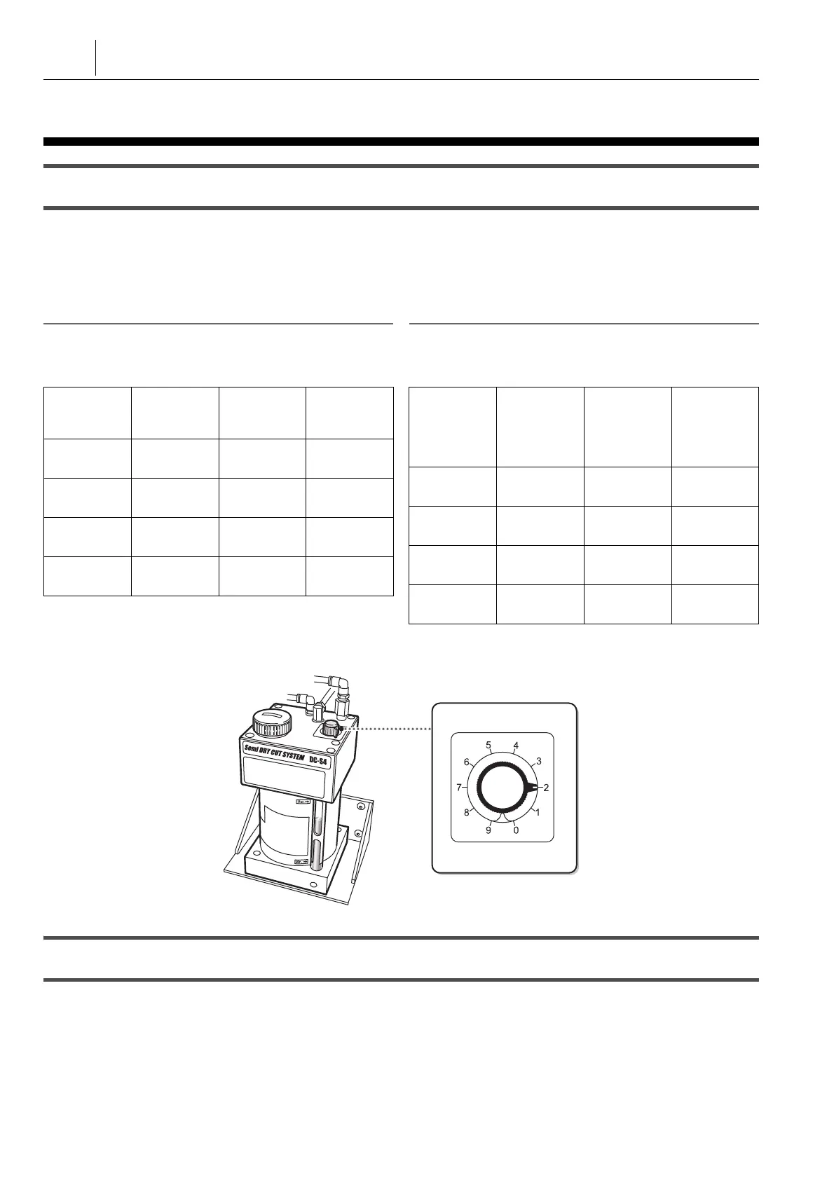
ᣮࢠɂบᦀᝩʘʠɥ “2” ȾᜫްȪȹȢȳȨȗǿบᦀᝩʘ
ʠɥ “2” ȾᜫްȪȲȻȠɁบ៵ᦀɂʘʄʵɑȲɂɴɮʵሰ
ɁՠȾȫȹ˩᚜ɁɛșȾ۰ԇȪɑȬǿҒҭసȾնɢȮ
ȹบᦀᝩʘʠȺΖፈᦀɥᝩȪȹȢȳȨȗǿ
Normally set the oil regulating knob at “2”. Oil consumption with
the oil regulating knob set at “2” varies according to the
diameter of the nozzle or the oil hole as shown in the chart
below. Adjust the setting with the oil regulating knob in
accordance with the cutting conditions.
2 าᜤ 2 NOTE
Ζፈɲɬ٢ɂǾ0.4 ᵻ 0.6 MPaᴥܟ 0.5 MPaᴦȾȪȹȢȳȨȗǿ The supplied air pressure should be 0.4 to 0.6 MPa (0.5 MPa
recommended).
ᴹบᦀᝩʘʠɥ “2” ȾᜫްȪȲȻȠɁบ៵ᦀᴻ <Oil consumption with oil regulating knob at “2”>
1 ᝊጯɂʅʩʓʳɮᚽᏚࠖɁᝢంɥՎྃȪȹȢȳȨȗǿ 1 Refer to the semi dry-cut system instruction manual published
separately for details.
15-2 บɁᛃፈ
Replenishing Oil
ᴹᬲᴻ <Procedure>
1) ൡಽໃɥȪɖȬɞǿ 1) Turn OFF the main power.
ɴɮʵሰɁ
ՠᴥሰ 1
ρɁکնᴦ
ɴɮʵሰɁ
ᬂሥ
ᴥ mm
2
ᴦ
պȫᬂሥ
Ⱥሰ 2 ρɁ
کն
บ៵ᦀ
ᴥcc/hᴦ
I3.0 mm 7.07
I2.12 mm u
2
12.4
I1.6 mm 2.01
I1.13 mm u
2
7.3
I1.0 mm 0.79
I0.71 mm u
2
0.8
I0.8 mm 0.50
I0.56 mm u
2
0.2
Diameter of
Oil Hole (1
oil hole)
Cross-Sec-
tion of Oil
Hole ( mm
2
)
2 Oil Holes
with the
Same
Cross-Sec-
tion
Oil Con-
sumption
(cc/h)
I3.0 mm 7.07
I2.12 mm u
2
12.4
I1.6 mm 2.01
I1.13 mm u
2
7.3
I1.0 mm 0.79
I0.71 mm u
2
0.8
I0.8 mm 0.50
I0.56 mm u
2
0.2
Oil Regulating Knob
บᦀᝩʘʠ
 Loading...