215
ӏࡾጀ࣊ȟҋȽȗȻȠ
WHEN SUB-STANDARD MACHINING OCCURS
2 าᜤ 2 NOTE
ȦɁȻȠǾȭɟɁᦀȟఊɕߴȨȢȽɞɛșȾ X ᢉɥӦʛʵʃᄉ
ႆبȺᝩȪȽȟɜͽഈɥᚐȶȹȢȳȨȗǿ
Perform X-axis adjustments using the manual pulse generator
during the above procedure to ensure deviation is reduced to the
minimum amount.
19) фᜏሰȠʦʵʒ 10 Ȟɥ፻ɔǾюɁȭɟᦀɥѓ࣊
ᆬᝓȬɞǿᛵȾȫȹǾᬲ 15) Ȼ 18) ɥᎱɝᣌȬǿ
19)Tighten the 10 hexagon socket head cap screws and
perform center-height deviation measurement. If
necessary, perform steps 15) and 18) again to readjust.
20) ϡᓸʞʽɁڋɔಃɥɝȤɞǿ 20)Replace the plug covering the eccentric pin.
21) ൡಽໃɥȪɖȬɞǿ 21) Turn OFF the main power.
22) ȹȦࣻʊɮʮʵɼ˂ʂȻผщɥɝ۶Ȭǿ 22)Remove the lever type dial test indicators from the
mounting jig.
23) ۶ȪȻᣡɁᬲȺǾҏ࿎իɁҰᬂɵʚ˂ȝɛɆϫᬂɵ
ʚ˂ɥɝȤɞǿ
23)Remount the turret front and side covers by following the
removal procedure in reverse.
24) ۶ȪȻᣡɁᬲȺǾҏ࿎իɁ֚ᣃɵʚ˂ᴥZ ᢉʡʷʐɹ
ʉȝɛɆɿʓʵϫᬂɵʚ˂ᴦɥɝȤɞǿ
24)Remount the turret surrounding covers (Z-axis protector
and saddle side cover) by following the removal procedure
in reverse.
25) ʫʽʐʔʽʃɵʚ˂ɥɝȤɞǿ 25) Remount the maintenance cover.
2 าᜤ 2 NOTE
ᝩǾᬲ 6) ȺขɔȲͱᏚɥ X ᢉɁژໄͱᏚȾᜫްȬɞᛵ
ȟȕɝɑȬɁȺǾࣷᇋɿ˂ʝʃᩌȾȧᣵፅȢȳȨȗǿ
Following adjustment, the point determined in step 6) must be set
in the parameters as the X-axis reference position. Contact the
Mori Seiki Service Department for assistance in performing this
procedure.
12-5 ઃիɁȭɟᝩ
Tailstock Center Adjustment
ʅʽʉӏࡾȺʹ˂ɹȟа܀ᴬаጯȾȽɞȻȠǾ˩ɁᬲȺ
ઃիɁȭɟɥᝩȪȹȢȳȨȗǿ
When primary taper or primary flare is generated on the
workpiece during center machining, adjust tailstock centering
according to the following procedure.
ᴹႊȬɞɕɁᴻ <Necessary Tools>
• ȹȦࣻʊɮʮʵɼ˂ʂ •Lever type dial test indicators
• ȹȦࣻʊɮʮʵɼ˂ʂȤผщ •Lever type dial test indicators mounting jig
• фᜏʶʽʋ •Hex wrench
• ʙʽʨ •Hammer
• ್ •Rod
ᴹᬲᴻ <Procedure>
1) X/Z ᢉᴥY ᢉറᴷX/Z/Y ᢉᴦɁՁཟ࢜ɥᚐșǿ 1) Perform a zero point return of the X- and Z-axes (Y-axis
specifications: X/Z/Y-axes).
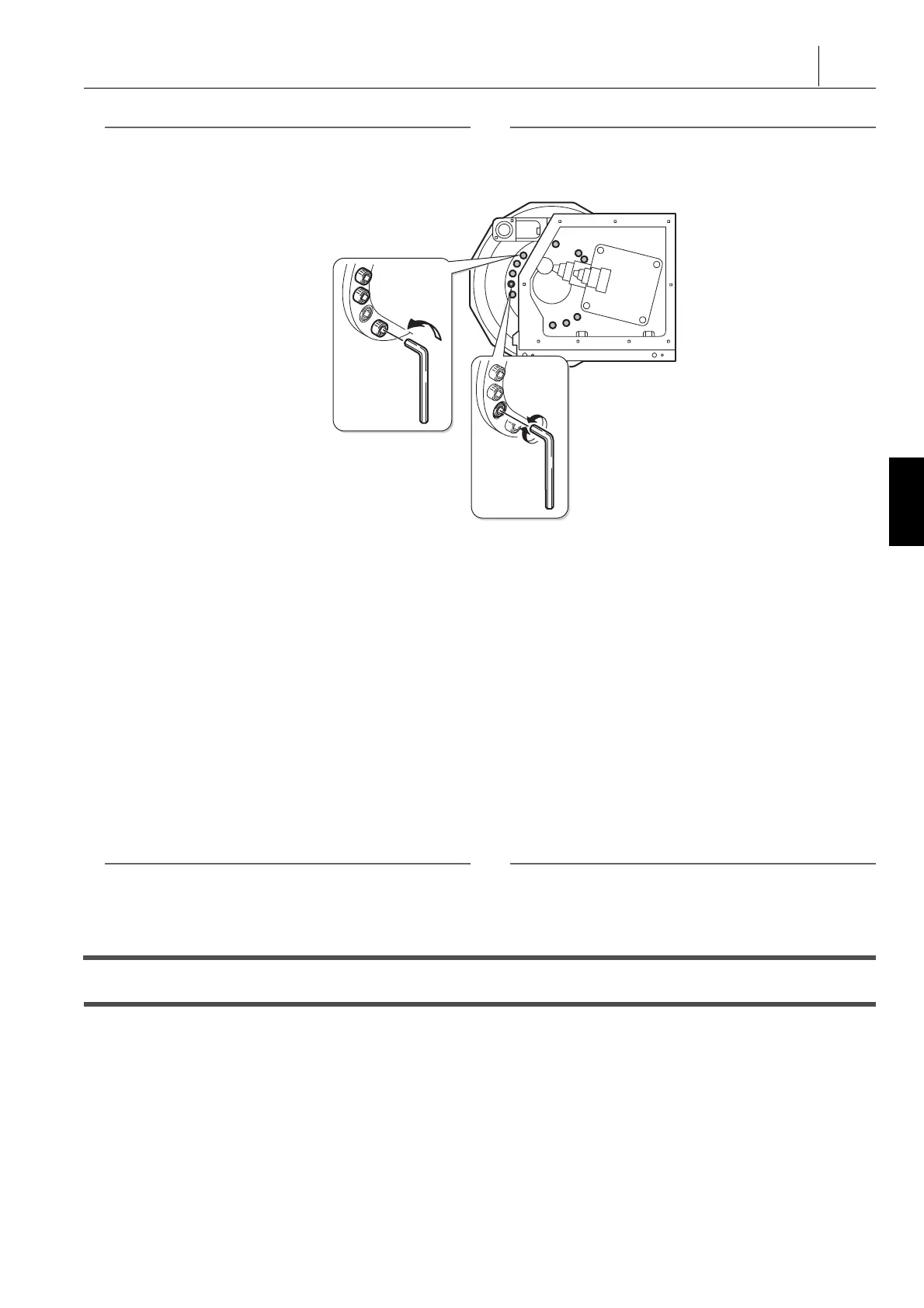
Cap Bolt Loosing (10)
Eccentric Pin Adjustment
ɷʭʍʡʦʵʒɁɔᴥ10 Ȟᴦ
ϡᓸʞʽɁᝩ
 Loading...