AP-51xx Access Point Product Reference Guide
2-14
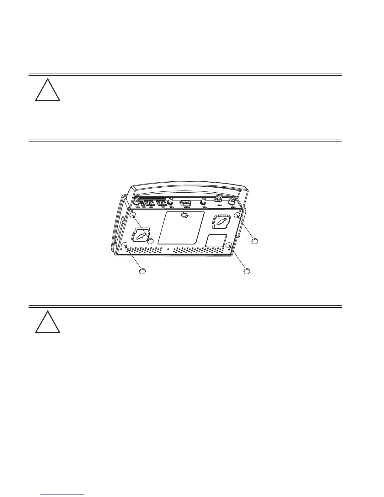
3. Remove the backings from the four (4) rubber feet and attach them to the four rubber feet
recess areas on the AP-5131.
4. Cable the AP-5131 using either the Power Injector solution or an approved line cord and
power supply.
For Power Injector installations:
a. Connect a RJ-45 Ethernet cable between the network data supply (host) and the power
injector Data In connector.
b. Connect a RJ-45 Ethernet cable between the Power Injector Data & Power Out
connector and the AP-5131 LAN port.
c. Ensure the cable length from the Ethernet source (host) to the Power Injector and
AP-5131 does not exceed 100 meters (333 ft). The Power Injector has no On/Off power
switch. The Power Injector receives power as soon as AC power is applied. For more
information on using the Power Injector, see Power Injector and Power Tap Systems on
page 2-10.
CAUTION Both the Dual and Single Radio model AP-5131’s use RSMA type
antenna connectors. On the Dual Radio AP-5131, a single dot on the
antenna connector indicates the primary antenna for both Radio 1 (2.4
GHz) and Radio 2 (5.2 GHz). Two dots designate the secondary
antenna for both Radio 1 and Radio 2. On Single Radio models, a
single dot on the antenna connector indicates the primary antenna for
Radio 1, and two dots designate the secondary antenna for Radio 1.
CAUTION Do not supply power to the AP-5131 until the cabling of the unit is
complete.
!
!

 Loading...