AP-51xx Access Point Product Reference Guide
2-28
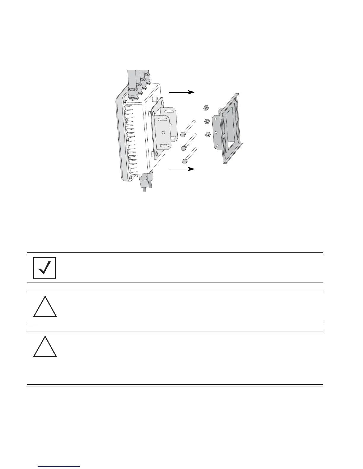
5. Use the included nuts to tightly secure the wireless bridge to the bracket. Fit the edges of
the V-shaped clamp into the slots on the flat side of the rectangular plate.
6. Attach the radio antenna to their correct connectors.
7. Cable the AP-5181 using either the AP-5181 Power Tap (Part No. AP-PSBIAS-5181-01R) or
the Power Injector (Part No. AP-PSBIAS-1P2-AFR).
a. Connect a RJ-45 Ethernet cable between the network data supply (host) and the Power
Tap’s DATA IN connector or the Power Injector’s Data In connector.
b. Connect a RJ-45 Ethernet cable between the Power Tap’s DATA/PWR OUT connector
or the Power Injector’s Data & Power Out connector and the AP-5181 LAN port.
NOTE Once ready for the final positioning of the access point, ensure the RJ45
cable connectors are oriented upwards to ensure proper operation.
CAUTION Do not supply power to the AP-5181 Power Tap or Power Injector until
the cabling of the access point is complete.
CAUTION For Power Tap installations, an electrician is required to open the
Power Tap unit, feed the power cable through the Line AC connector,
secure the power cable to the unit’s three screw termination block and
tighten the unit’s Line AC clamp (by hand) to ensure the power cable
cannot be pulled from the Power Tap enclosure. Only a certified
electrician should conduct the installation.
!
!

 Loading...