Troubleshooting Charts: RX RF Failure 5-31
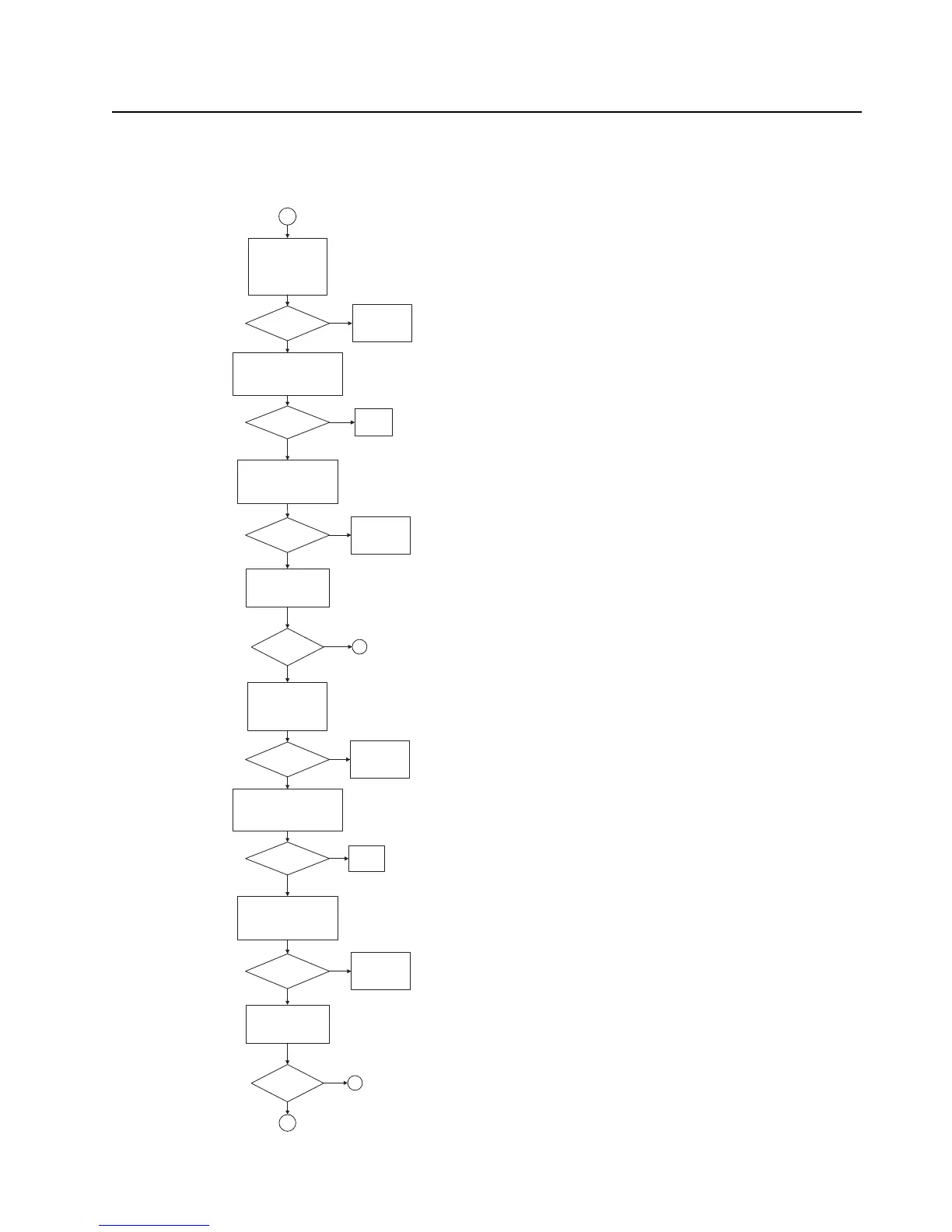
RX RF Failure – Page 5
4
Remove shield, SH9.
Measure RF levels at the
RF switch, U402, and
compute switch loss.
800: output side of C402
& input side of R450.
Loss < 2 dB?
No
Measure RF levels at the SAW
filter, FL401, and compute filter
loss.
800: output side of R450 and
output side of C412.
Loss < 2 dB?
No
Replace
FL401
Measure RF levels at the RF
switch, U404, and compute
switch loss.
800: output side of C412 &
output side of C487.
Loss < 2 dB?
No
Yes
Measure RF levels at LNA
and compute LNA gain.
800: input side of C423
and output side of R406.
Gain about
8 dB?
Yes
No
Yes
Yes
Measure RF levels at the
RF switch, U403, and
compute switch loss.
800: output side of R406
& input side of R452.
Loss < 1 dB?
No
Measure RF levels at the SAW
filter, FL402, and compute filter
loss.
800: output side of R452 and input
side of R454.
Loss < 3 dB?
No
Measure RF levels at the RF
switch, U405, and compute
switch loss.
800: output side of R454 & input
side of C430.
Loss < 1 dB?
No
Yes
Measure RF levels at LNA
and compute LNA gain.
800: input side of C430
and output side of R412.
Gain about
8 dB?
Yes
No
Yes
Yes
Replace
FL402
5
6
7
Check digital logic
to the RF switch
and replace U402
if needed.
Check digital logic
to the RF switch
and replace U404
if needed.
Check digital logic
to the RF switch
and replace U403
if needed.
Check digital logic
to the RF switch
and replace U405
if needed.
Note: RF Test frequency used:
UHF1: 424.975MHz
UHF2: 485.075MHz
VHF: 154.275MHz
700: 769.0625MHz
800: 860.0625MHz
Measured with a High Frequency Probe for relative comparisons and troubleshooting
only. Actual S21 gain or loss may differ if the test point is not 50 ohms.

 Loading...


