5-32 Troubleshooting Charts: RX RF Failure
RX RF Failure – Page 6
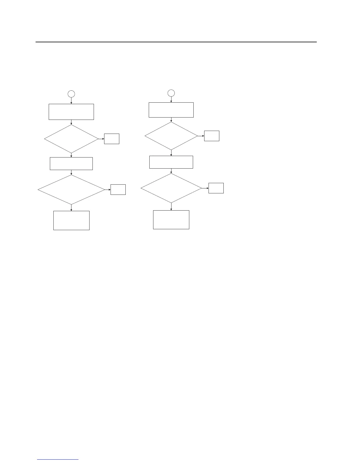
Check LNA:
Check DC bias voltages for U406
at the base (pin 1) & collector (pin
3).
Is base voltage =
0.778 V? and
collector voltage =
1.554 V?
Check DC bias voltages of Q402
at the base (pin 2 or 5) , collector
(pin 6) & emitter (pin 1).
Is base voltage = 1.024
V? Collector voltage =
0.777 V? Emitter voltage
= 1.554 V?
Check DC input line
voltages and visually
inspect and replace
defective components if
needed.
No
Yes
No
Yes
Replace
U406
Replace
Q402
Check LNA:
Check DC bias voltages for U407
at the base (pin 1) & collector (pin
3).
Is base voltage =
0.778 V? and
collector voltage =
1.552 V?
Check DC bias voltages of Q403
at the base (pin 2 or 5), collector
(pin 3) & emitter (pin 4).
Is base voltage = 1.025
V? Collector voltage =
0.778 V? Emitter
voltage = 1.552 V?
Check DC input line
voltages and visually
inspect and replace
defective components if
needed.
No
Yes
No
Yes
Replace
U407
Replace
Q403
6
7
Note: RF Test frequency used:
UHF1: 424.975MHz
UHF2: 485.075MHz
VHF: 154.275MHz
700: 769.0625MHz
800: 860.0625MHz
Measured with a High Frequency Probe for relative comparisons and troubleshooting
only. Actual S21 gain or loss may differ if the test point is not 50 ohms.

 Loading...


