7-10 Troubleshooting Tables: List of Board and IC Signals
NC NC W15
I/O Pullup Input Pull-
down
NC NC R10
I/O Pullup Input Pull-
down
uart1_tx UART1 Serial
Transmit Data
Y14
Output None 0 Output Pull-
down
uart1_rx UART1 Serial Receive
Data
V14
Input Pullup Input Pull-
down
uart1_rts UART1 Request To
Send (output)
AA15
Output None 0 Output Pull-
down
uart1_cts UART1 Clear To Send
(input)
R14
Input Pullup Input Pull-
down
uart3_tx UART3 Serial
Transmit Data
M18
Output None 0 Output Pull-
down
uart3_rx UART3 Serial Receive
Data
L14
Input Pullup Input Pull-
down
usb1_txen USB1 Transmit
Enable
W16
0 Output None Input None
usb1_data USB1 Bidirectional
Data
W14
I/O None 0 Output Pull-
down
usb1_se0 USB1 Bidirectional
Single Ended Zero
R13
I/O None U Output Pull-
down
usb0_txen USB0 Transmit
Enable
W4 0 Output None 1 Output Pull-
down
usb0_data USB0 Bidirectional
Data
P9
I/O None Input None
usb0_se0 USB0 Bidirectional
Single Ended Zero
R8
I/O None Input None
ssi_omap_clock SSI Clock into OMAP G21
Input None Input None
ssi_omap_sync SSI Sync into OMAP H15
Input None Input None
ssi_omap_txd SSI Serial Data from
CODEC
H20
Input None Input Pull-
down
ssi_omap_rxd SSI Serial Data to
CODEC
H18
Output None 0 Output Pull-
down
spi_arm_clk ARM SPI Clock from
OMAP
U19
I/O Pull-
down
Input None
spi_arm_mosi ARM SPI Data from
OMAP
W21
I/O Pull-
down
0 Output Pull-
down
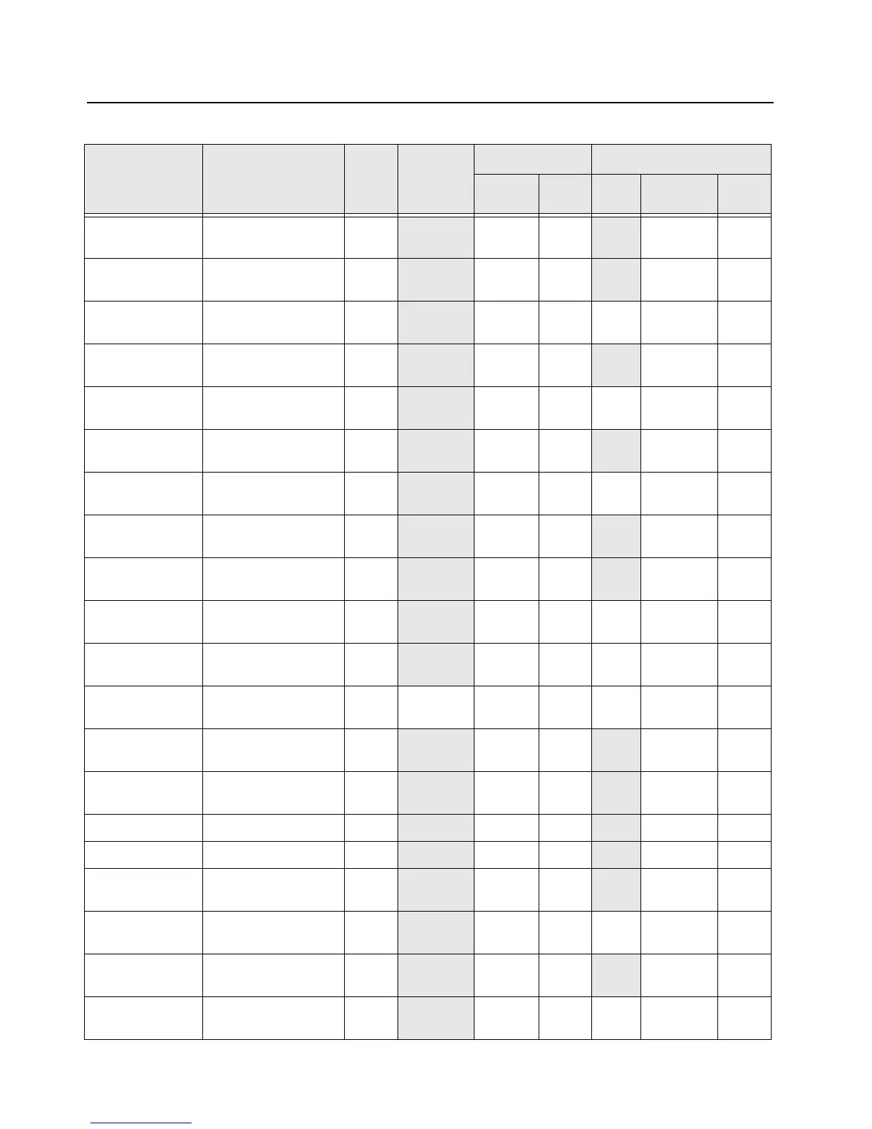
Table 7-7. Overall GPIO pin functions (Continued)
Signal Name Description
Pin or
Ball #
Active State
SW Initialized HW Reset
Direction
*
PU State Direction
*
PU
or
PD

 Loading...


