EasyManuals Logo

Motorola APX 6000 Service Manual

Motorola APX 6000
438 pages
To Next Page IconTo Next Page
To Previous Page IconTo Previous Page
Page #262 background imageLoading...
Page #262 background image
7-12 Troubleshooting Tables: List of Board and IC Signals
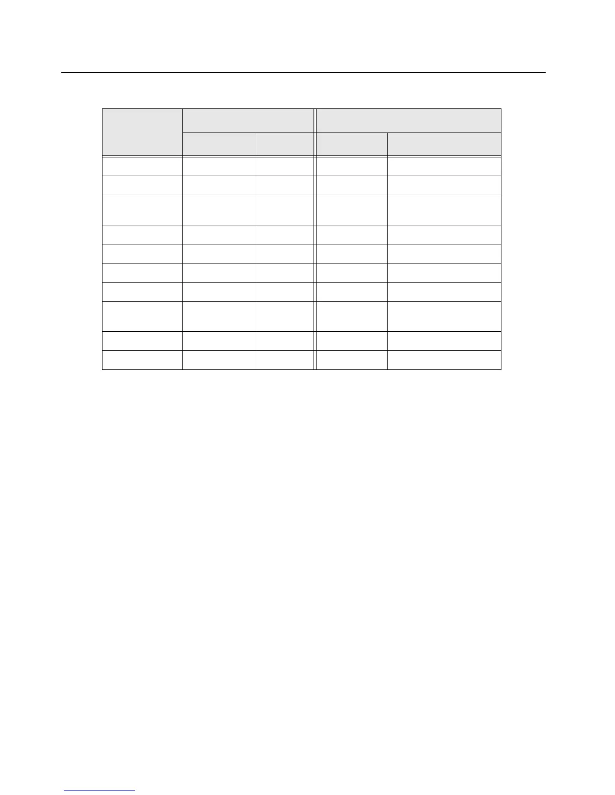
Table 7-8. EXPANSION board to Side Buttons Interface PIN-OUT
Test Place
VOCON Board Side Buttons
signal name pin # pin # signal name
chassis GND J2005-1 P1-1 GND
chassis GND J2005-2 P1-2 GND
R2012 CON_MONIT
OR_1
J2005-3 P1-3 MON_B
R2011 CONN_SB2_1 J2005-4 P1-4 SB_2_B
chassis GND J2005-5 P1-5 GND
chassis GND J2005-6 P1-6 GND
R2010 CONN_SB1_1 J2005-7 P1-7 SB_1_B
R2009 CON_INT_PT
T_1
J2005-8 P1-8 PTT_B
chassis GND J2005-9 P1-9 GND
chassis GND J2005-10 P1-10 GND

Table of Contents

Other manuals for Motorola APX 6000

Questions and Answers:

Question and Answer IconNeed help?

Do you have a question about the Motorola APX 6000 and is the answer not in the manual?

Motorola APX 6000 Specifications

General IconGeneral
Frequency Range700/800 MHz, VHF, UHF Range 1, UHF Range 2
IP RatingIP67
P25 Phase 1 & 2Yes
GPSYes
EncryptionAES, DES
Power Output1-3 Watts (700/800 MHz)
Operating Temperature-30°C to +60°C
Intrinsically SafeYes
BluetoothYes (Bluetooth 4.0)

Related product manuals