Theory of Operation: Controller 3-49
3.2.6.3.2 Secondary Lighting Controller
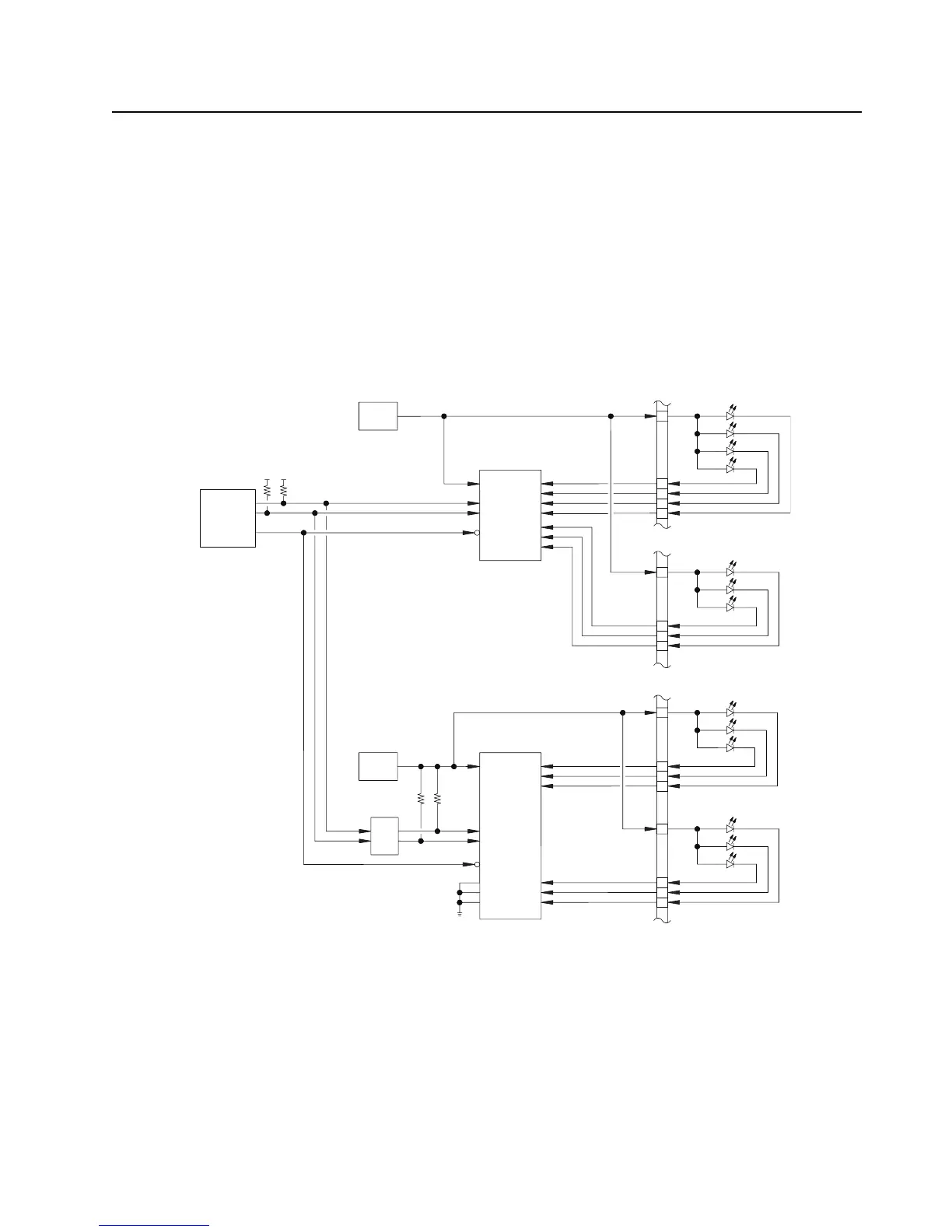
As previously mentioned the secondary lighting controller provides illumination to the top display
backlight and Tx/Rx indicator lamp. The lighting controller and LEDs are powered by switcher 5
(V_SW_5). This lighting controller device uses a PWM output to control the dimming modes of
operation for each LED. The device is controlled through the I2C interface, however, the I2C
interface require an input high voltage between 3 V – 5.5 V, thus the level translator (U2202) is used
to boost these signals to 5V logic.
Figure 3-34 shows the major connection scheme to this secondary lighting controller. The white,
green, and red top display LEDs are connected to the lighting controller PWM outputs through ESD
filter inductors L2204, L2203, L2202, respectively. The TX/RX status indicator LED uses a tri-color
red, green, amber (RGA) LED.
Figure 3-34. Lighting Controller Overview
FRONT DISPLAY
LED DRIVER
(LM27965)
10
VIN
V_SW_3.6
V-REG
VOUT
KEYPAD
12
20
21
11
15
16
17
18
D1A
D2A
D3A
D4A
D1B
D2B
D3B
RESET
SCL
SDIO
OMAP
RST_OUT
(I2C) SCL
(I2C) SDA
LED DRIVER
(LP3943)
PWR
LED0
V_SW_5
V-REG
VOUT
RESET
SCL
SDA
LED1
LED2
LED4
LED5
LED6
A0
A1
A2
LEVEL
SHIFT
1.85V
1
TOP DISPLAY
25
15
17
8
26
24
23
R
G
W
A
G
R
FRONT DISPLAY
WHITE BACKLIGHT
KEYPAD WHITE
ILLUMINATION
TX/RX
STATUS
TOP DISPLAY
BACKLIGHT

 Loading...


