3-62 Theory of Operation: Accelerometer
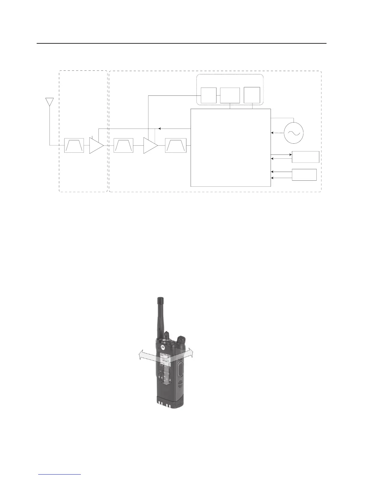
Figure 3-43. GPS Block Diagram (UHF1 and UHF2)
3.4 Accelerometer
3.4.1 General Overview
Accelerometer capabilities are achieved by the 3-axes “nano” accelerometer IC (LIS331DL) located
on the expansion board. The LIS331DL is a digital output linear accelerometer in a LGA package. It
is powered by the 3.3 LDO regulator placed in the expansion board. The complete device includes a
sensing element and an IC interface to provide the signal to the AVR IC. When acceleration is
applied to the sensor, an imbalance in capacitance is produced. This imbalance is measured and
converted to an analog voltage that is finally available to the user by an analog to digital converter.
The acceleration data is accessed through an SPI interface and presented to the AVR.
Figure 3-44. Directions of the Detectable Accelerations
NOTE: Please refer to User Guide and CPS for further details.
GPS IC
TI NL5500
GPS_LNA_IN (L2)
GPS_EXT_LNA_EN (H6)
TCXO_CLK_LV (F1)
TCXO
26MHz,
<0.5ppm
GPS_UART_TX (F5)
GPS_UART_RX (E3)
UART2 Rx (R9)
UART2 Tx (M18)
[OMAP 1710]
GPS Tx
GPS Rx
GPS_NSHUTDOWN (D5)
RTC_CLK (H9)
32kHz RTC
[CPLD]
IO74 (E2)
IO91 (D12)
Reset
External Regulators
1.8V
(VCC_1.85)
2.8V
LNA Enable
LNA
Expansion Board
nt
LNA
RF Board
RF-VOCON-Exp
Interconnect
3.6V
(VSW_3.6)
3.0V
SAW SAW
VDD_TCXO (G1)
VBAT VDDS
SAW
X
Y
Z

 Loading...


