3-30 Theory of Operation: Controller
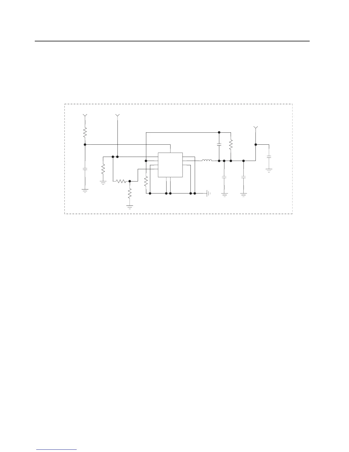
3.2.2.1.2 External Regulators: V_SW_1.4, V_SW_3.60
The controller board contains two TPS62050 regulators in order to regulate voltages of 1.4V and
3.6V. The TPS62050 is a synchronous step-down adjustable regulator. The switching regulator is
capable of sourcing 800mA. Its output can be adjusted by using a voltage divider tied to the feedback
pin. The regulators are powered from SW_B+. Figure 3-17 is the schematic for the V_SW_1.4
regulator that illustrates the supporting circuitry for the TPS62050.
Figure 3-17. V_SW_1.4 Switched Power Supply
V_1.55
10UF
4.7UF
C6586C6584
330PF
C6570
R6568
V_SW_1.4
301K
C6582
L6505
6.8PF
10UH
SW1V4_FB
U6507
TPS62050
SW_B+
VCC_SW1.4_VIN
R6548
R6554
R6558
R6552
R6547
C6569
DNP
0
10UF
0
0
165K
100K
EN
PG
VIN
FB
GND
LBI
SYNC
PGND
SW
LBO
1
7
9
10
4
26
3
5
8

 Loading...


