Troubleshooting Tables: List of Board and IC Signals 7-21
RF_BRD_ID_BI
T_0
RF Board ID bit 0 16 1 Input PU Input None
ATTENUATORS
_ON
Controls the front end
attenuators for both VHF
and 7/800 MHz, but
NOT in Tx. The
peregrine switch does
not have a mode where
it can be placed in TX
while attenuating the RX
path.
17 1 Output
Input None
RF_BRD_ID_BI
T_1
RF Board ID bit 1 18 1 Input PU
Input None
UNUSED1 Not connected. 19 1 Output
Input None
RF_BRD_ID_BI
T_2
RF Board ID bit 2 21 1 Input PU
Input None
REMOTE_ANTE
NNA_ACTIVE
Remote antenna select 22 1 Output
Input None
H66_H68_PATH
_ACTIVE
Selects path for VHF
transmit, UR1 and UR2.
23 1 Output
Input None
800RX_FRONT_
END_ACTIVE
Enables the 800 path in
the RX front end.
25 1 Output
Input None
ALL_TX_ONLY_
EXCEPT_VHF_
TX
Enables RF path 1
(VCO page). On for all
transmit modes except
VHF transmit. Off for all
RX modes
27 1 Output
Input None
H66_VCO_PATH
_ON
selects H66 VCOs path 29 1 Output Input None
NONE OMAP GPIO1
determines default state
of some EMIFS pins.
Latched on rising edge
of PWR_ON_RESET.
Pulled low on PCB
R19
Input PD 0 Input PD
NONE Unused, defaults to
UART2.BCLK in reset
mode 0. PD on PCB
Y4 Output None 0 Output None
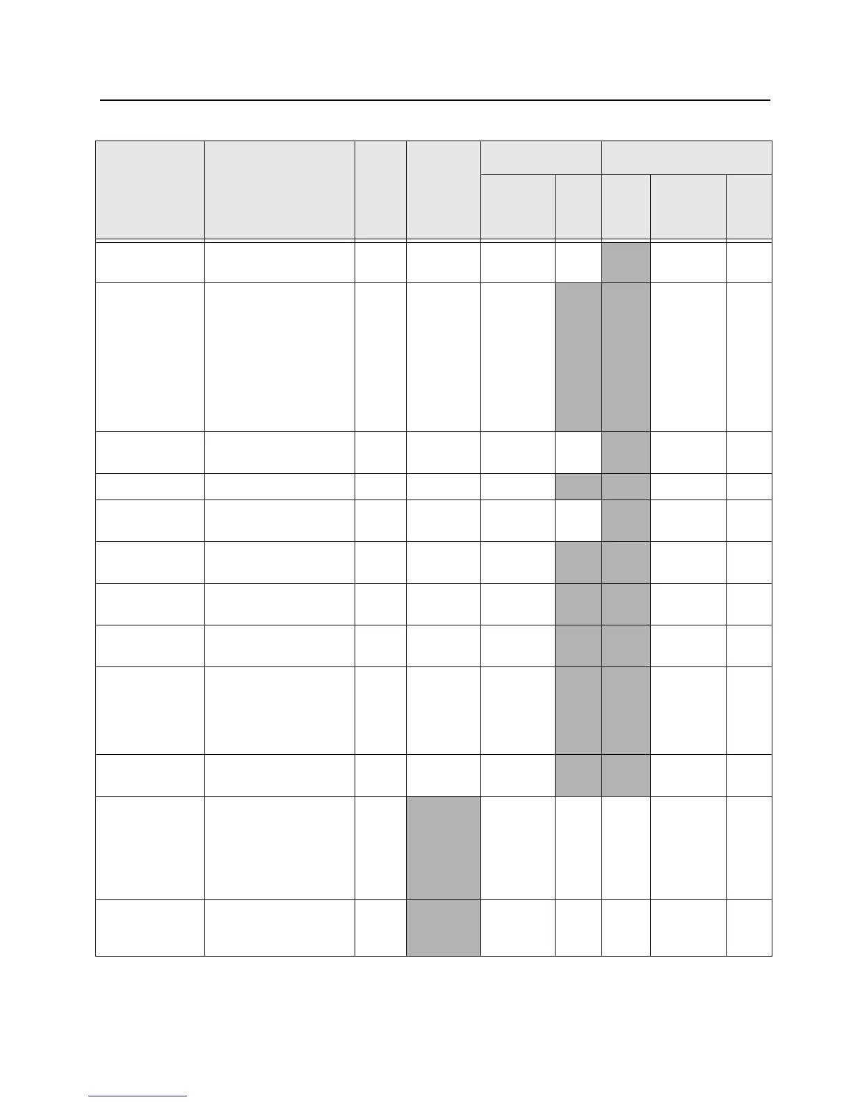
Table 7-12. Overall GPIO pin functions across multiple boards (Continued)
Signal Name Description
Pin
or
Ball #
Active
State
SW Initialized HW Reset
Direction
*
PU State Direction
*
PU
or
PD

 Loading...


