Troubleshooting Tables: List of Board and IC Signals 7-23
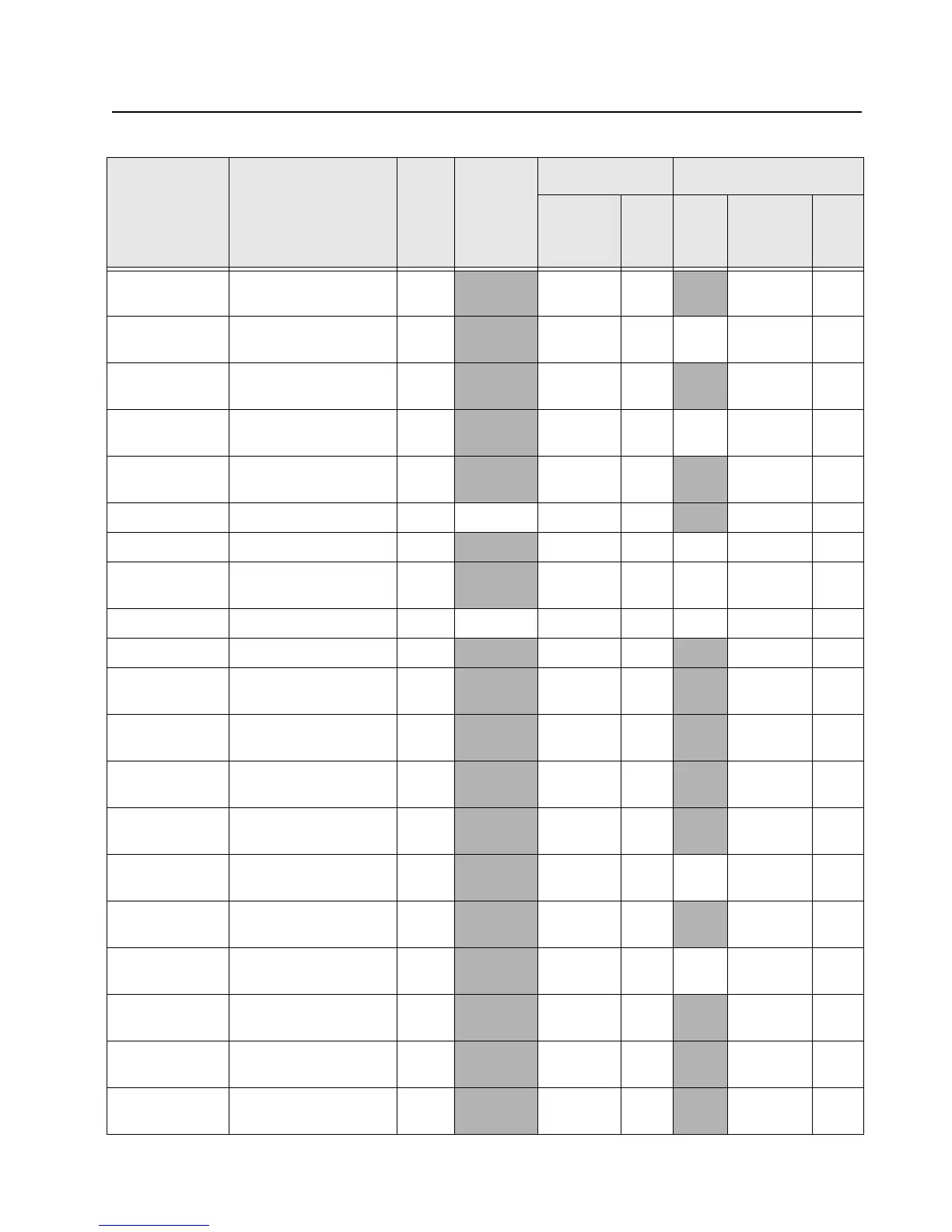
UART1_RX UART1 Serial Receive
Data
V14 Input PU Input PD
UART1_RTS UART1 Request To
Send (output)
AA15
Output None 0 Output PD
UART1_CTS UART1 Clear To Send
(input)
R14
Input PU Input PD
UART3_TX UART3 Serial Transmit
Data
M18
Output None 0 Output PD
UART3_RX UART3 Serial Receive
Data
L14
Input PU Input PD
USB1_TXEN USB1 Transmit Enable W16 0 Output None
Input None
USB1_DATA USB1 Bidirectional Data W14
I/O None 0 Output PD
USB1_SE0 USB1 Bidirectional
Single Ended Zero
R13
I/O None U Output PD
USB0_TXEN USB0 Transmit Enable W4 0 Output None 1 Output PD
USB0_DATA USB0 Bidirectional Data P9
I/O None Input None
USB0_SE0 USB0 Bidirectional
Single Ended Zero
R8
I/O None Input None
SSI_OMAP_CL
OCK
SSI Clock into OMAP G21
Input None Input None
SSI_OMAP_SY
NC
SSI Sync into OMAP H15
Input None Input None
SSI_OMAP_TX
D
SSI Serial Data from
CODEC
H20
Input None Input PD
SSI_OMAP_RX
D
SSI Serial Data to
CODEC
H18
Output None 0 Output PD
SPI_ARM_CLK ARM SPI Clock from
OMAP
U19
I/O PD Input None
SPI_ARM_MOSI ARM SPI Data from
OMAP
W21
I/O PD 0 Output PD
SPI_ARM_MISO ARM SPI Data into
OMAP
U18
Input PD Input PD
SPI_DSP_CLK DSP SPI Clock from
OMAP
N14
I/O PD Input None
SPI_DSP_MOSI DSP SPI Data from
OMAP
P14
Output PD Input PD
Table 7-12. Overall GPIO pin functions across multiple boards (Continued)
Signal Name Description
Pin
or
Ball #
Active
State
SW Initialized HW Reset
Direction
*
PU State Direction
*
PU
or
PD

 Loading...


