6809495A43-C April 03, 2006 39
Level 1 and 2 Service Manual Disassembly
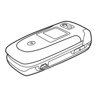
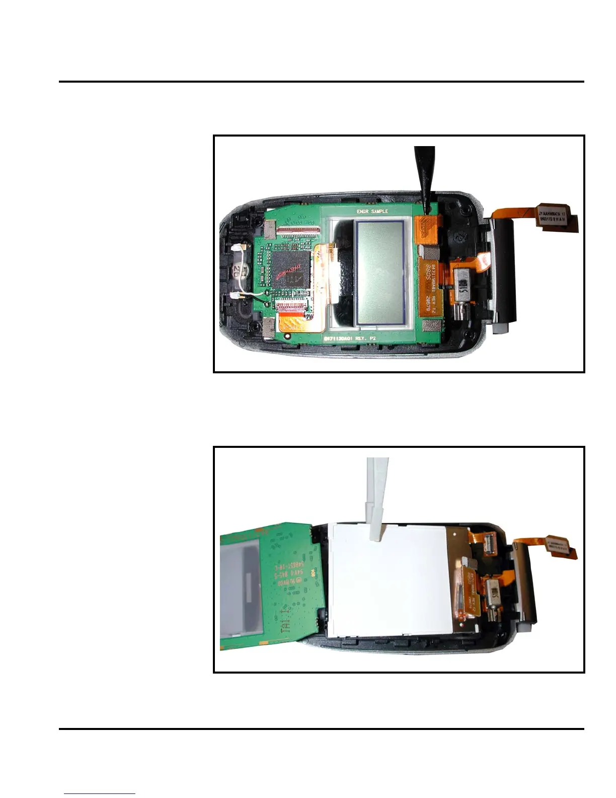
3. Use the disassembly tool to unseat the display module flex connector (see
Figure 20).
4. Turn the display module printed circuit board over and use the plastic tweezers
to lift away the display module from the flip (see Figure 21).
050495o
Figure 20. Camera Assembly Flex Connector Removal
050496o
Figure 21. Display Module Removal
 Loading...