26 April 14, 2004 6809471A72-O
Disassembly V80
Removing and Replacing the Transceiver Board Assembly
1. Remove the battery cover, battery, SIM, antenna housing, rear housing assem-
bly, and camera assembly as described in the procedures
.
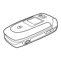
2. Using the plastic disassembly tool, disconnect the display flex connector from
its socket on the transceiver PCB assembly (See Figure 10).
G
This product contains static-sensitive devices. Use anti-static handling procedures
to prevent electrostatic discharge (ESD) and component damage.
G
The flexible printed cable (FPC) (flex) is easily damaged. Exercise extreme care when
handling.
032300o
Figure 10. Removing the Display Flex Connector
G
The flex is fragile and easily damaged. Be very careful when passing the flex through
the transceiver PCB opening.
 Loading...