Performance Checks
12
Initial equipment control settings should be as indicated in the Table 5, and should hold for
all alignment procedures except as noted.
Display Radio
Test Mode
Entering Display
Radio Test Mode
1. Turn the radio on.
2. Within 10 seconds after “Self Test” is complete, press Side button 3 five times in
succession.
3. The radio will show a series of displays that will give information regarding various
version numbers and subscriber specific information. The displays are described in
Table 6.
NOTE: All displays are temporary and will disappear without
any user intervention. If information is longer than the
physical length of the radio’s display, the information
will wrap around to the next display. After the last
display, “RF TEST” will be displayed. For non-display
radios, refer to the CPS Radio Information Screen.
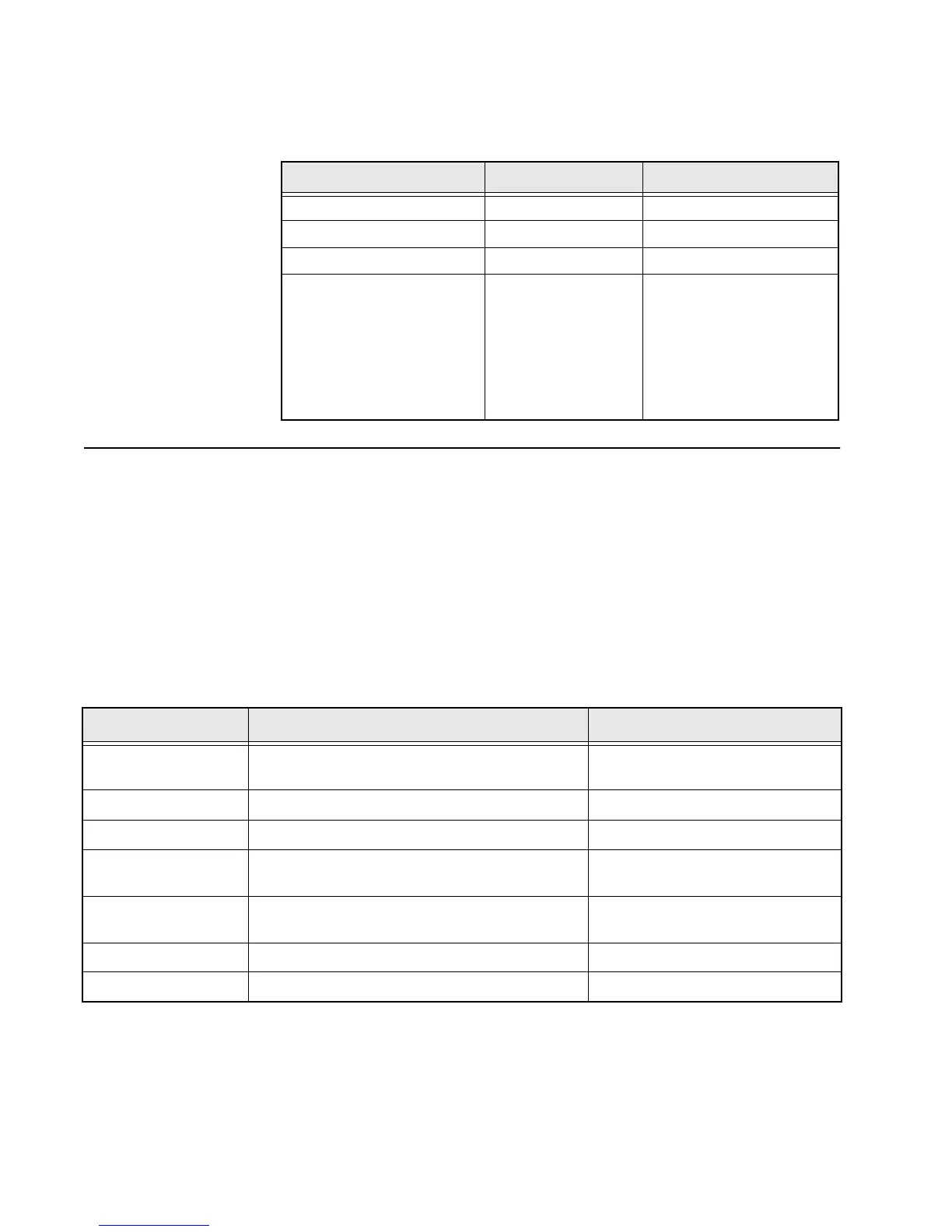
Table 5. Initial Equipment Control Settings
System Analyzer Test Set Power Supply
Monitor Mode: Pwr Mon Spkr Set: A Voltage: 7.5Vdc
RF Attn: –70dB Spkr/Load: Speaker DC On/Standby: Standby
AM, CW, FM: FM PTT: OFF (center) Volt Range: 10Vdc
O'scope Source: Mod
O'scope Horiz: 10mSec/Div
O'scope Vert: 2.5 kHz/Div
O'scope Trig: Auto
Monitor Image: Hi
Monitor BW: Nar
Monitor Squelch: Mid CW
Monitor Vol: 1/4 CW
Current: 2.5Amps
Table 6. Front-Panel Access Test-Mode Displays
Name of Display Description Appears
“SERVICE” The literal string indicates the radio has entered test
mode.
Always.
Host Software Version The version of host firmware. Always.
DSP Software Version The version of DSP firmware. Always.
Model Number The radio’s model number as programmed in the
codeplug.
Always.
Serial Number The radio’s serial number as programmed in the
codeplug.
Always.
ROM Size The memory capacity of the host FLASH part. Always.
FLASHcode The FLASH codes as programmed in the codeplug. Always.

 Loading...


