Disassembly/Assembly
45
10. Carefully lift the latches on the main circuit board to release the flexible circuits from
their connectors.
NOTE: For proper reassembly, note how the flex circuits are
folded.
11. Remove the concentric lever from the front cover assembly.
Chassis
Disassembly
For this section, please refer to the Model III exploded view and parts list on page 35 for
part numbers and more information on the location of parts in the radio.
1. If disassembly of the chassis or the main board is required, then use a TORX™
screwdriver with a T7-IP head to remove the five screws holding the main board and
shield to the chassis.
2. Remove the O-ring from around the bushing at the antenna connector
3. Lift the main board from the chassis as shown in Figure 32.
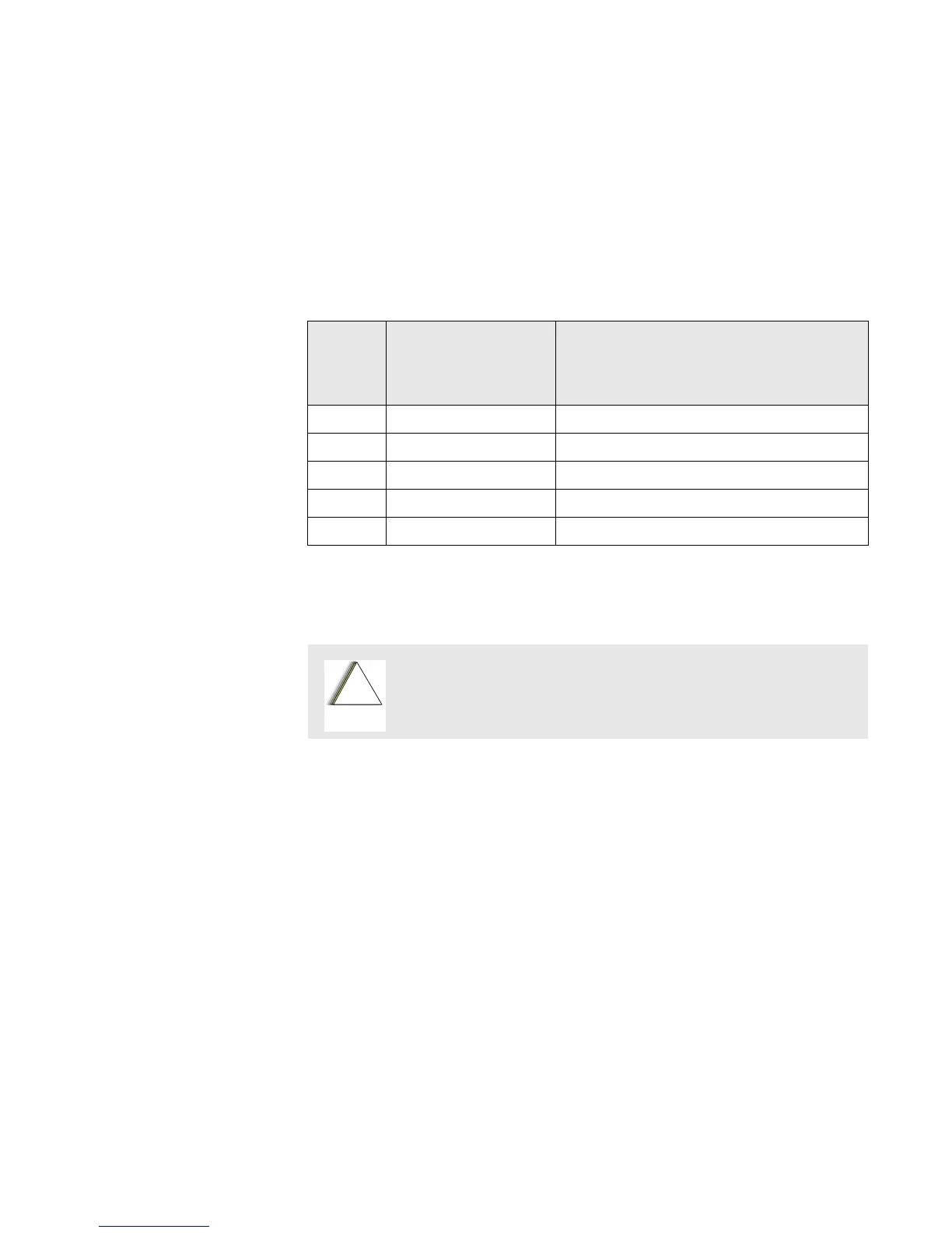
Table 17. Chassis Disassembly
Exploded
View
Item
Number
Motorola Part Number Description
19 0385563D01 Screw (5 required)
21 2785787C01 Chassis Cover, Rear
22 3285270D01 Seal, Main O-ring
34 2685785C01 Main Shield
35 Typical Main Board
Refer to the Handling Precautions on page 4 before removing the
main board. Be sure to use ESD protection when handing circuit
boards.
!
C a u t i o n

 Loading...


