Performance Checks
13
4a. Press Side Button 1 to stop the displays and put the radio into the Control Top and
Keypad test mode (display radio). The test mode menu “CH TEST” will be
displayed. Go to the “Control Top and Keypad Test Mode (Display Radio)” section
on page 14.
NOTE: Each press of Side Button 1 will toggle between “CH TEST” and
“RF TEST.”
OR
4b. Press the Top Programmable Button to stop the displays and put the radio into the
RF test mode (display radio). The test mode menu “1 CSQ.” will be displayed,
indicating test frequency 1
, Carrier SQuelch mode. Go to “RF Test Mode (Display
Radio)” in the next section.
RF Test Mode
(Display Radio)
When the ASTRO Digital XTS 2500 radio is operating in its normal environment, the radio's
microcomputer controls the RF channel selection, transmitter key-up, and receiver muting,
according to the customer codeplug configuration. However, when the unit is on the bench for
testing, alignment, or repair, it must be removed from its normal environment via a special
routine, called TEST MODE or “air test.”
1. Each additional press of Side Button 3 will advance to the next test channel. (Refer
to Figure 7.)
2. Pressing Side Button 2 will scroll through and access test environments as shown in
Figure 8.
NOTE: Transmit into a load when keying a radio under test.
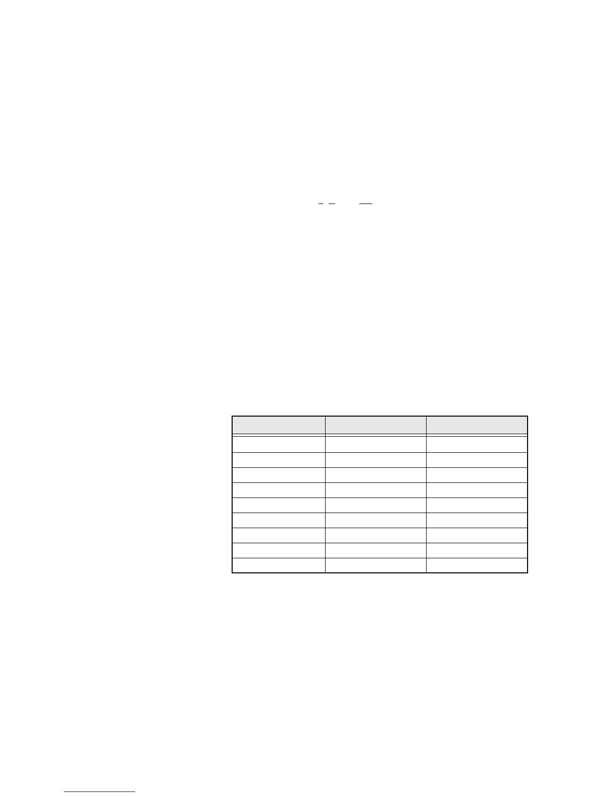
Table 7. Test Frequencies
Frequency 700/800 MHz RX 700/800 MHz TX
F1 764.0625 764.0125
F2 769.0625 769.0125
F3 775.9375 775.9875
F4 851.0625 794.0125
F5 860.0625 809.0125
F6 869.9375 823.9875
F7 851.0625 851.0125
F8 860.0625 860.0125
F9 869.9375 869.8875

 Loading...


