ioLogik E1200 Series Using the Web Console
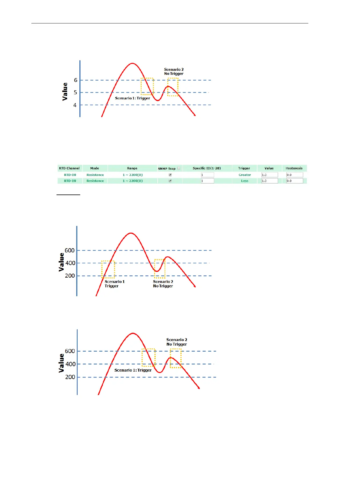
When Trigger = less, Value = 5, and Hysteresis = 1, the SNMP trap will only be triggered if the analog signal
fluctuates from 6 to 5, as depicted in Scenario 1 below. However, if we change the settings to Value = 5 and
Hysteresis = 2, the SNMP trap will only be triggered if the analog signal fluctuates from 7 to 5.
RTD Input Trap Settings
For RTD Input, the trap is triggered when the RTD input meets the preset conditions for Trigger, Value, and
Hysteresis. Refer to RTD Channel settings to set the Mode and Range.
Example:
When Trigger = Greater, Value = 400 and Hysteresis = 200, the SNMP trap will only be triggered if the RTD
signal fluctuates from 200 to 400, as depicted in Scenario 1 below. However, if we change the settings to Value
= 400 and Hysteresis = 400, the SNMP trap will only be triggered if the RTD signal fluctuates from 0 to 400.
When Trigger = less, Value = 400, and Hysteresis = 200, the SNMP trap will only be triggered if the RTD signal
fluctuates from 600 to 400, as depicted in Scenario 1 below. However, if we change the settings to Value = 400
and Hysteresis = 400, the SNMP trap will only be triggered if the RTD signal fluctuates from 800 to 400.
 Loading...