6 Installation and commissioning
74 5831400/02 EN
3. Connect the wires at the free end of the connection cable in the control
cabinet in accordance with the supplied connection diagram.
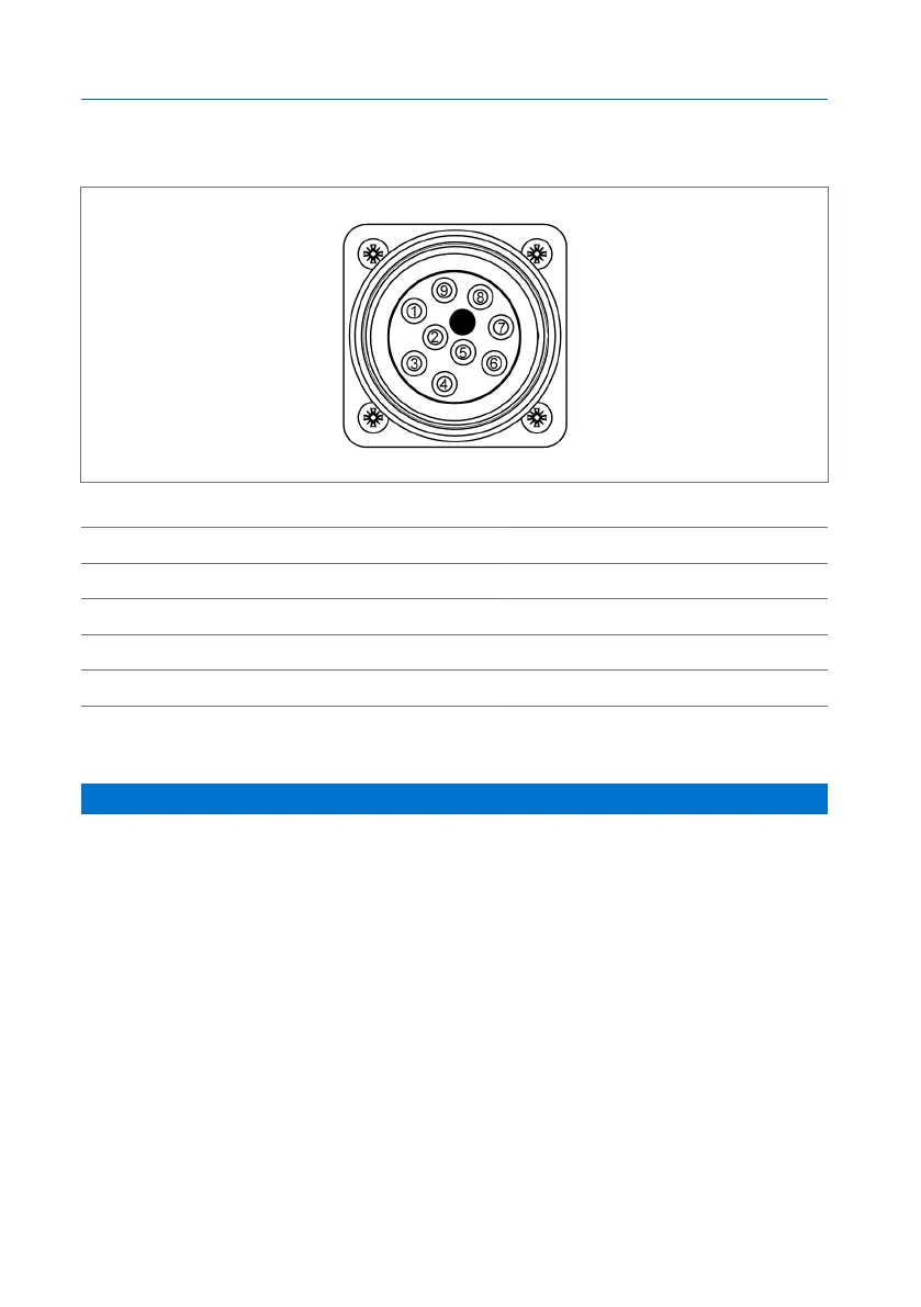
Figure56: Connection assignment, view of installed ANSI connector
1 Black 2 Red
3 Blue 4 Orange
5 Yellow 6 Brown
7 Red/black 8 Blue/black
9 Orange/black
6.4.8 Connecting cable glands/NPT adapters
NOTICE
Damage to the device!
The supplied locking screws are intended to protect the device from mois-
ture and the like during transport. If you do not use any locking screws or if
you use the wrong ones, the IP55 degree of protection and the necessary
flame protection cannot be guaranteed.
Metal locking screws are available as accessories.
► Seal unneeded cable glands/NPT adaptors with suitable locking screws
and gaskets to ensure the IP55 degree of protection and the flame pro-
tection.
► Screw the locking screw into the unused connection.