6 Installation and commissioning
495831400/02 EN
6.4.4 Cable glands and adapters
► NOTICE! If cable glands or adapters are not used, these must be sealed
with suitable seals and metal locking screws to ensure the IP55 de-
gree of protection and flame protection of the device.
Metal locking screws are available as accessories:
▪ Brass locking screw: material no. MS960750
▪ Stainless steel locking screw: material no. 781711
For assembly, see Sealing cable glands/NPT adapters [►Section 6.4.8,
Page 74].
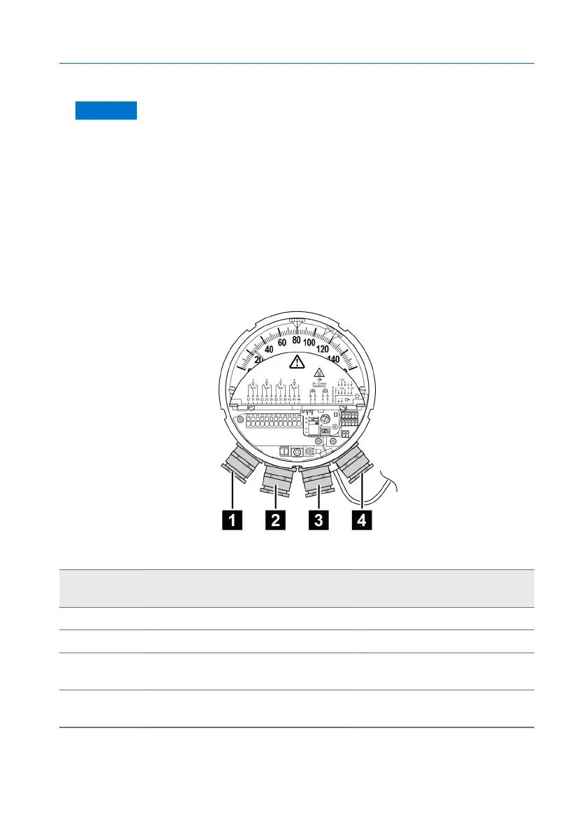
Cable gland assignment
Figure25: Cable gland assignment
Steps to
perform
Assignment Note
1 2x change-over contacts and PE
2 2x change-over contacts
3 Input (and output) for Modbus and
supply voltage
EMC double cable gland
4 Input current transformer signal and
4...20mA analog output
EMC double cable gland
Table7: Example wiring (maximum assignment)