6 Installation and commissioning
675831400/02 EN
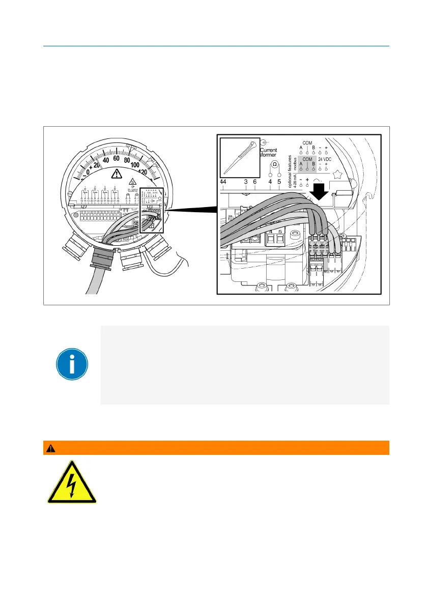
Connecting the Modbus RTU in accordance with the connection
diagram
► Use the same method to attach the wires for the Modbus RTU to the ter-
minals "A", "COM" and "B". Do so by pushing the wires through the
opening up to the stop.
Figure50: Connecting Modbus
The circuit board provides the possibility to loop through the
RS-485 connection to the next device (daisy-chain) via the
second terminal strip.
If the device is the only bus device or the last bus device, in-
sert a terminating resistor (120Ω, 0.5W) into the second ter-
minal strip between "A" and "B".
6.4.7 Connecting the micro-switches
WARNING
Electric shock
The micro-switches may be connected either to only extra-low-
voltage circuits or to only low-voltage circuits. Mixed voltages
are not permitted.