6 Installation and commissioning
86 5831400/02 EN
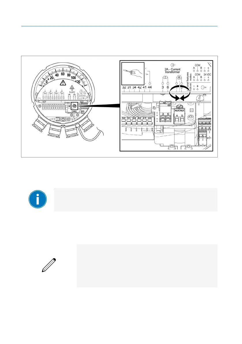
4. Set the required resistance value using the adjusting screw of the poten-
tiometer. Turning the adjusting screw to the right causes the resistance
value to increase, and turning it to the left causes it to decrease.
Figure68: Potentiometer adjusting screw
5. Remove the measuring device.
6. Put the bridge back in terminals 4 and 5 and tighten the lock screws.
Since you are not working with the actual heating current dur-
ing this setting process, we recommend a second calibration
before commissioning.
Temperature gradient calibration before commissioning:
Example:
Displayed temperature without current source: 40°C
Nominal secondary transformer current: 1.9A
Required gradient: 26K
Temperature display after gradient adjustment: 40°C
+ 26K = 66°C
ü The thermometer is mounted on the transformer.
1. Note the temperature currently shown on the thermometer (e.g. 40°C).