Installation
Control Unit Models 9010 LCD and 9020 LCD
13
GB
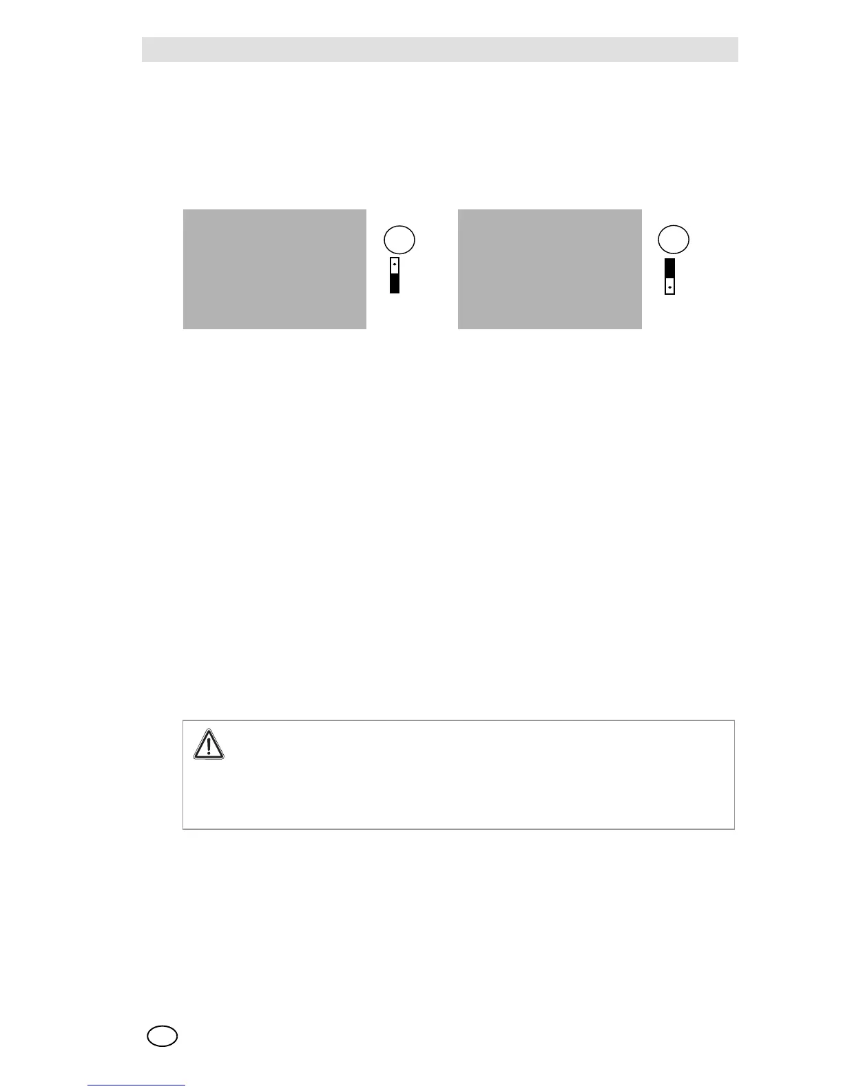
Predisposition for supplying auxiliary external circuits via the Control Unit
In the cases in which direct current is not available and makes it necessary to supply the auxiliary
circuits external to the Control Unit [e.g. relays, interfaces, transmitters, etc.], it is possible to pro-
vide 24 VDC at the heads of the terminals 4 [+] e 5 [-] predisposing jumper CV18 in position 1-2.
The maximum power that can be connected depended on the transformer mounted on the
Control Unit and on the sensors/transmitters used. This exit is protected by a 2-amp fuse F3.
For any technical problem, please contact the MSA Technical Support Department.
Sensor or transmitter connections
In the cases in which the Control Units are supplied in a pre-calibrated state for the required gas,
it is necessary for each sensor, identified by a serial number, to be connected to the Control Unit
or to the channel [A or B in the case of model 9020] which records the same number.
When the Control Units are connected to transmitters 4/20 mA, they can be freely connected with
respect to the particular configurations.
The connection of the sensor to the Control Unit must be carried out, unless there are different
instructions on the part of MSA, via shielded cable.
The number of conductors necessary for the connection of the sensor, planned during configura-
tion, is indicated on the CALIBRATION DATA SHEET attached to the Instruction Manual while, in
order to know the minimum section that must be used, depending on the current consumed by the
sensor and on the length of the line, consult the diagrams attached to the manual.
The shielding of the connection cable to the sensor must be uniquely connected to the
screw or to the faston earth terminal adjacent to the back terminal board for connection of
the Control Unit, it is important that the shielding from the sensor side be carefully isolated
and absolutely not be connected to the earthing screw that is located inside the sensor
case. The case must be connected to earth via a different conductor to be fixed to the
screw predisposed on the outside of the box.
If it were necessary to employ more lengths of cable between the Control Unit and sensor, it is
necessary to make the joints via welds; it is a good rule of thumb to make welds also on the wire
terminals.
TRANSFORMER TRANSFORMER
Fig. 10 24 VDC Power Supply from internal source Fig. 11 24 VDC Power Supply from external source