Appendix
Control Unit Models 9010 LCD and 9020 LCD
53
GB
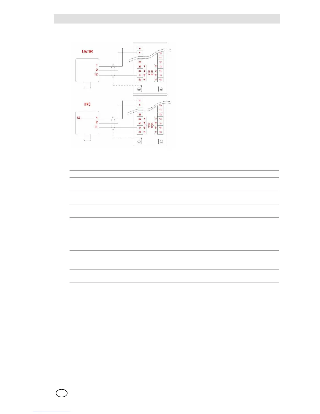
9010/20 LCD rev3-Connections with Flame Detector Transmitters
Configuration 9010/20 LCD
Board 9010 LCD rev 3 Board 9020 LCD rev 3
4/20 mA board
article no.
10093585 10093584
General purpose
board article no.
10093583 10093582
Simulation
module article no.
10063804
Hardware configu-
ration
The 4/20 mA board does not require any configuration and is predisposed for
connection with 2-wire and/or 3-wire MSA transmitters.
The configuration of the jumpers on the general purpose board is done in the
factory as per Tables 2 and 3
Both the versions are configured with internal power supply [Cv 18 item 1-2]
Config. software The configuration of the board has been done in the factory, recalling the
configuration as per the Calibration Data Sheet is accomplished with
Access Code 53 P2 .
NOTES The Ir3 detector model 20/20 requires an internal jumper between terminals
1 and 12 for the 4/20 mA source type output