Control Unit Models 9010 LCD and 9020 LCD
50
Appendix
MSA
GB
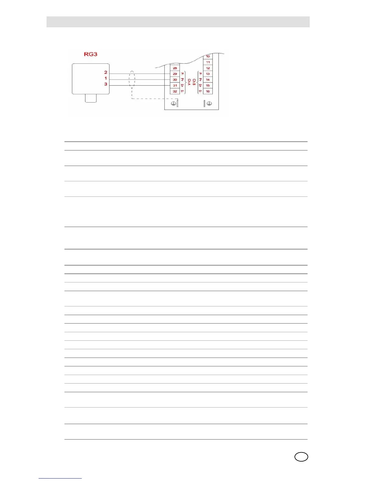
9010/20 LCD rev3-Connections with RG3 transmitter
Configuration 9010/20 LCD
Typical data of RG3 transmitter
Board 9010 LCD rev 3 Board 9020 LCD rev 3
4/20 mA board
article no.
10093585 10093584
General purpose
board article no.
10093583 10093582
Simulation mod-
ule article no.
10063804
Hardware configu-
ration
The 4/20 mA board does not require any configuration and is predisposed for
connection with 2-wire and/or 3-wire MSA transmitters.
The configuration of the jumpers on the general purpose board is done in the
factory as per Tables 2 and 3
Config. software The configuration of the board has been done in the factory, recalling the
configuration as per the Calibration Data Sheet is accomplished with
Access Code 53 P2.
RG3 NOTES
Power supply 10 30 VDC
24 VDC current consumption Approx. 130 mA With catalytic sensor
Output signal 4 - 20 mA and Rs 485 4/20 mA source type
output
St. operating temperature -20 °C +55 °C
Transmitter weight 2500 g
Dimensions 119x119x125
Container material Aluminium
Connection cable data
Cable type Shielded at least 80 %
Max. load at output 4-20 mA 600 Ohms 24 VDC
Maximum connection distance as a function of the electrical power supply
Board power supply 115/230 VAC / 24 VDC
U.C. 9010 LCD rev3 U.C. 9020 LCD rev.3
RG-3 relay board and
catalytic sensor 47.7
1000 m 750 m
The data refer to the nominal voltages and with a wire having a 1.5 mm² section
Distances must be derated by 25-30 % approx. if nominal voltages drop by 15-20 %
For other data or more details, consult the specific manual or contact the Technical Support
Department