EasyManuals Logo

MSA 9020 LCD User Manual

MSA 9020 LCD
99 pages
To Next Page IconTo Next Page
To Previous Page IconTo Previous Page
Page #22 background imageLoading...
Page #22 background image
Control Unit Models 9010 LCD and 9020 LCD
22
Configuration
MSA
GB
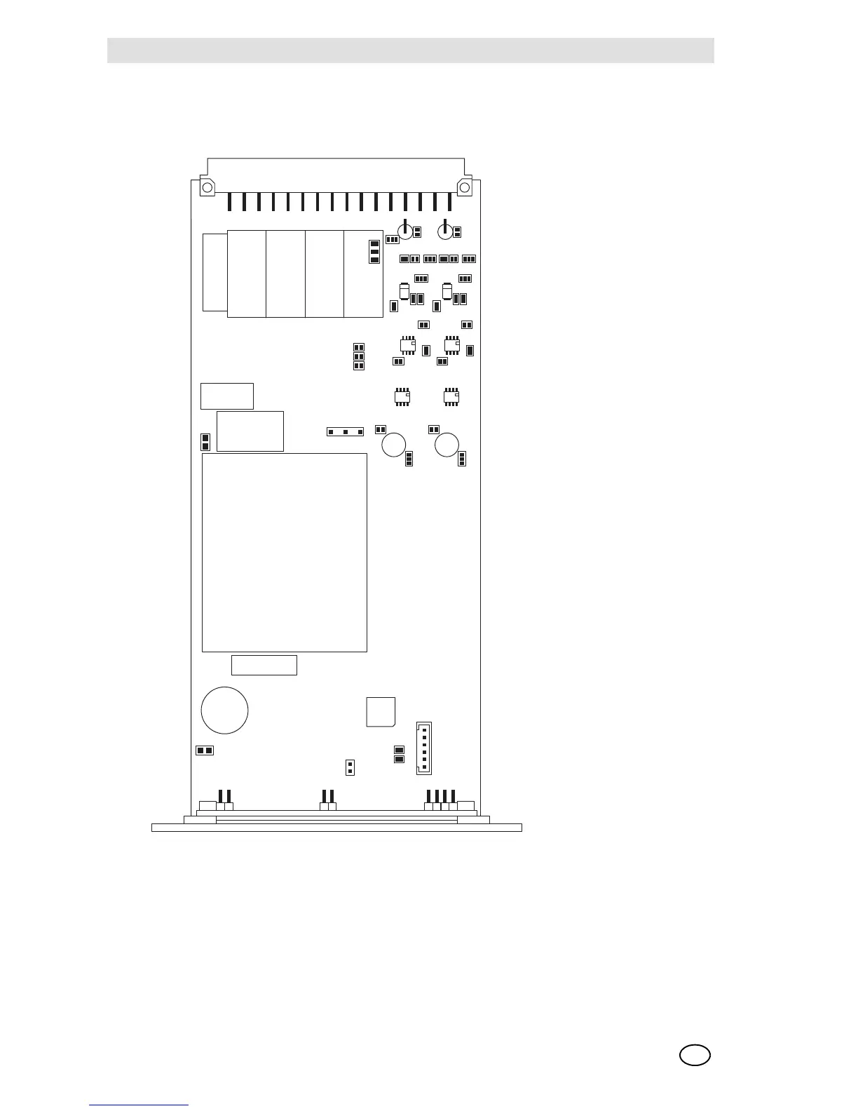
For the location of the jumpers, consult the accompanying topographical diagram.
Board 9010/20 LCD with article no. 10093585 / 10093584 for individual 2-wire or 3-wire 4/20 mA
inputs, has the following hardware predispositions, which are recommended not to be modified:
Cv3, Cv4, Cv 6, Cv8, Cv9 pos 1-2, Cv10.
Fig. 12 Jumpers
CV22
**CV19
123
CV3A
CV3B
CV5A
CV2A
CV13A
CV5B
CV2B
CV13B
1
2
3
1
2
3
1
2
3
1
2
3
1
2
3
CV9A
CV9B
CV4A
CV12A
CV11A
CV4B
CV12B
CV11B
CV6A
CV6B
CV8A
CV7A
CV8B
CV7B
CV15
CV16
CV17
CV10A
CV10B
1
2
3
CV1A
1
2
3
CV1B
1
2
3
CV13
CV14
CV20
CV25
CV24 CV23
**CV19 PLACE ON SOLDER LAYER

Table of Contents

Questions and Answers:

Question and Answer IconNeed help?

Do you have a question about the MSA 9020 LCD and is the answer not in the manual?

MSA 9020 LCD Specifications

General IconGeneral
BrandMSA
Model9020 LCD
CategoryControl Unit
LanguageEnglish

Related product manuals