Installation
Control Unit Models 9010 LCD and 9020 LCD
11
GB
4 Installation
4.1 Mechanical installation
The control units 9010/20 LCD are constructed to be installed in various configurations; versions
are available for mounting in 3HE racks, in wall-mount versions in one- or two-point ABS contain-
ers or 4-point metal containers or in ADPE containers for installations in hazardous zones; custom
solutions can be implemented by customer request.
A correct installation must avoid environments that are particularly humid, oxidising, corrosive,
subject to notable vibrations or in which the excursions of temperature exceed the limits indicated
in the TECHNICAL CHARACTERISTICS section.
In the cases in which the installation is planned in cabinets, heed the prevailing standards that
govern the maximum permissible temperature inside these same cabinets, in any case the instal-
lation of the racks in the cabinets must be carried out in such a way as not to impede the natural
ventilation of the various electronic components of the boards.
It is helpful is there is adequate space between one rack and another.
Sufficient space needs to be left at the back of the rack to allow for correct connection of the con-
ductors to the back terminal boards.
The dimensions of the containers and the weights are recorded in the diagrams and drawings sec-
tion.
4.2 Electrical installation
Make the various electrical connections [power supply, sensors, alarms, etc.] to the back terminal
of the Control Unit consulting the specific EXTERNAL CONNECTIONS DIAGRAM with relay or
opto-isolated output.
Use electrical conductors suitable for the power values recorded in the
TECHNICAL CHARACTERISTICS; the rack, in the rear part, is equipped with two bars for affixing
and supporting the cables connected to the back terminal boards of the Control Unit.
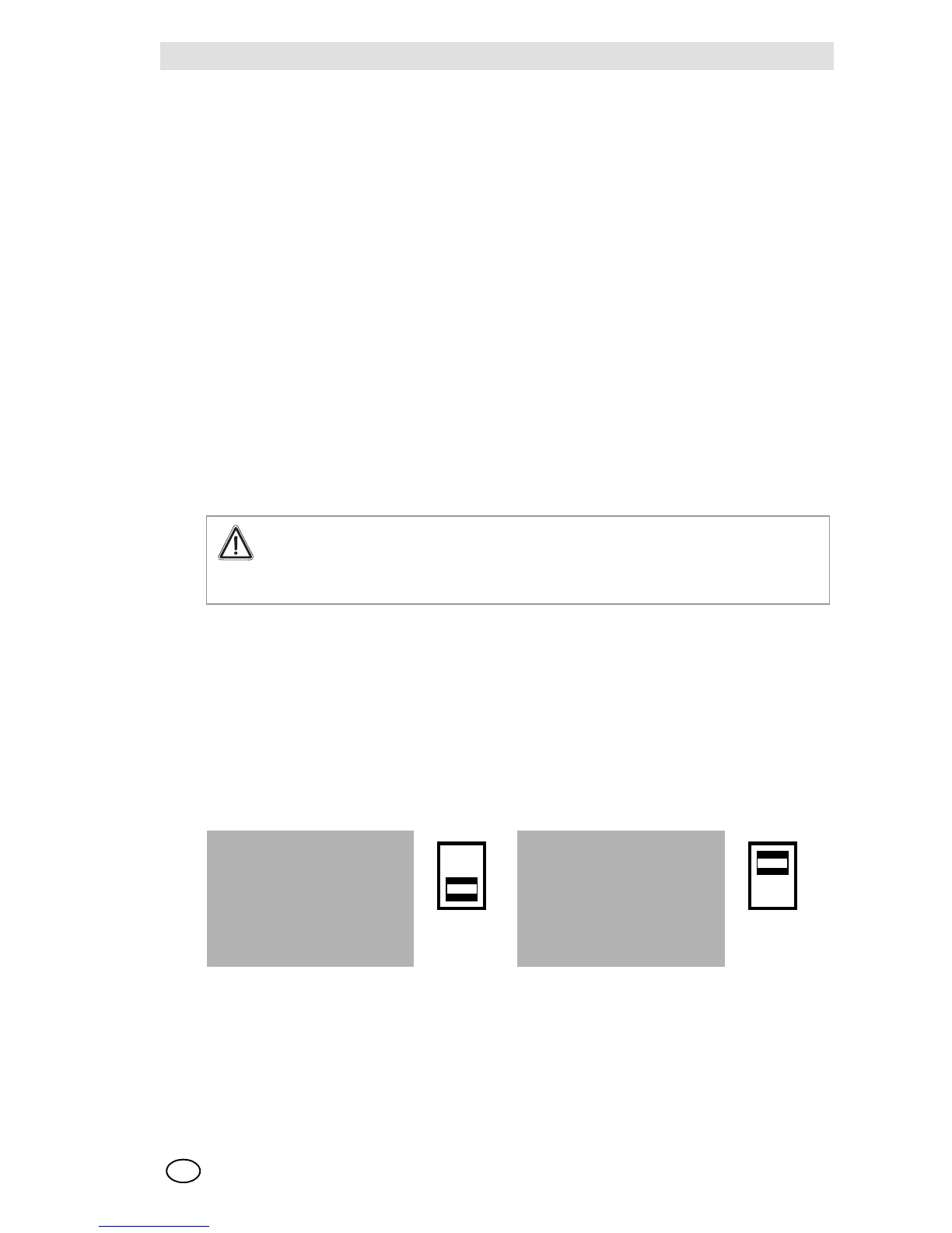
Power supply from electrical mains
The Control Units 9010/20 LCD can be fed in alternating current from the electrical mains at a
voltage of 115 VAC ±15 % or 230 VAC ±15 % depending on the predisposition represented be-
low, which is carried out using the appropriate selector.
Attention!
The electrical installation needs to be carried out by qualified personnel in compliance
with the prevailing standards, especially in areas where there is an explosion and fire
hazard.
TRANSFORMER TRANSFORMER
Fig. 8 Power Supply 230 VAC Fig. 9 Power Supply 115 VAC