18
Installation
6. Verify the sensor connector is firmly seated on the terminal board.
7. Attach the sensor's ground to either of the grounding screws inside the TG5000 back plate.
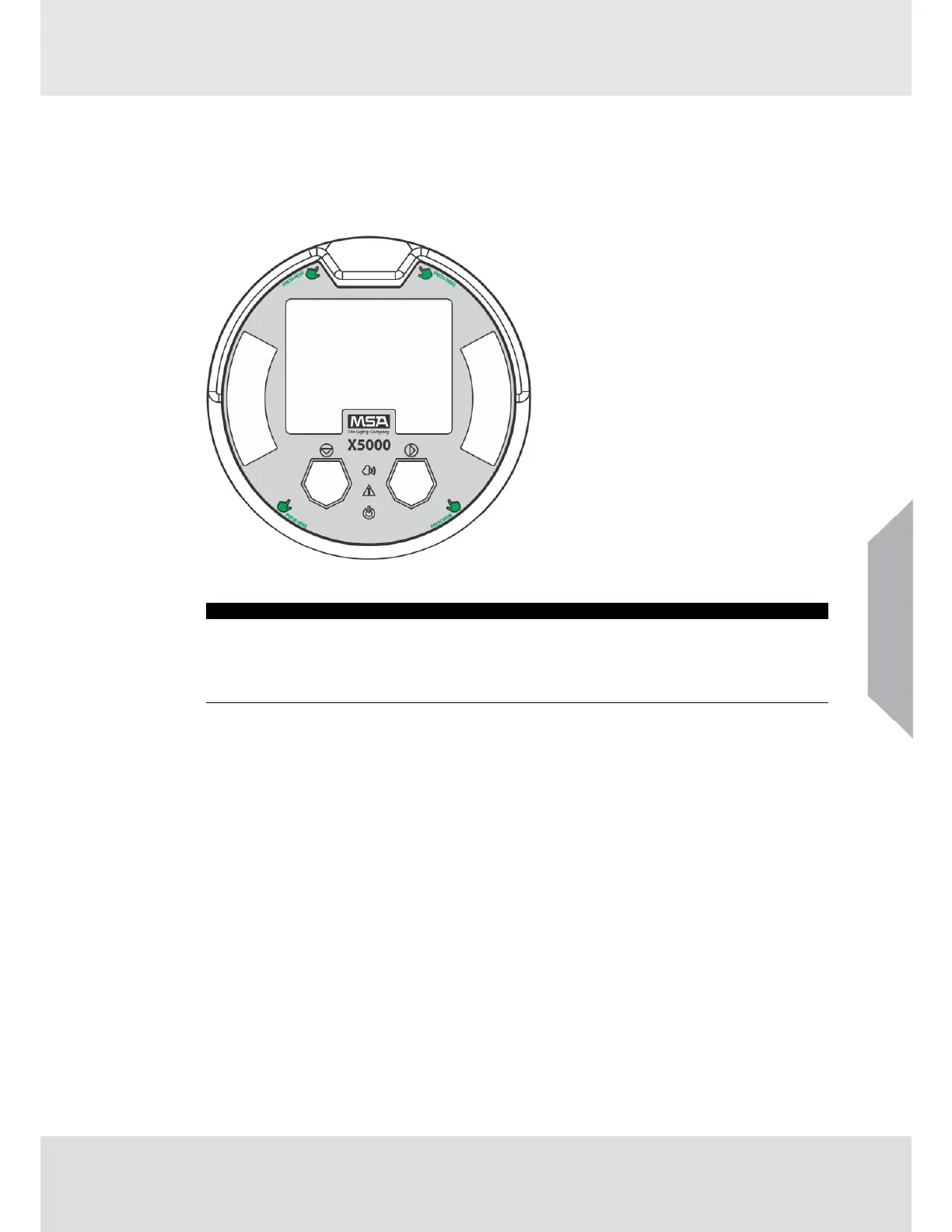
8. Replace the board stack legs into the four depressions in the mounting plate. Push firmly
on the board stack where indicated (see Fig. 10).
Fig. 10 Highlighted Areas Show Where to Press when Replacing a Board Stack
NOTICE
Avoid pressing on the left and right areas where the LEDs are located. Pressing
directly on the display will damage the display and will void the warranty.
Ensure that the electronics assembly is fully engaged in the mounting holes. If not
fully seated, the user interface buttons may not function properly.
9. Replace the enclosure cover.
US