29
Installation
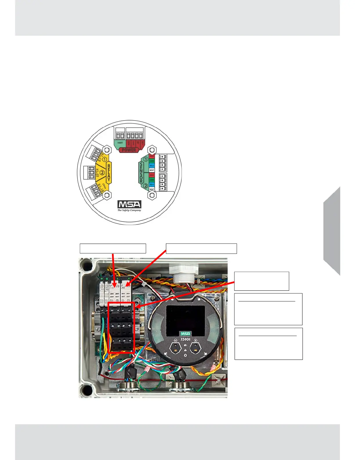
3.4.4 Relay and Power Connections
Relay Board Stack Overview
The TG5000 Relay pack is configured from the two alarm relays on the PCB board stack.
Relays 1 and 2 from the PCB board stack operate the integral strobe, sounder and user
relay dry contacts. No other connections should be made to the relays 1 and 2 on the PCB
board stack (see Fig. 23A). No user connections should be made to the two dedicated horn
silence relays on the TG5000 Relay pack terminal strip. Users should connect only connect
to the Low Alarm Relay 3 and High Alarm Relay 4. (see Fig. 23B)
The third relay on the PCB board stack is a dedicated fault relay (see Fig. 24). This relay
can be used for field connections to monitor the fault status of the TG5000.
This relay is labeled for Normally Open (NO) and Normally Closed (NC) de-energized state.
Fig. 23A ULTIMA X5000 PC Board with Relays
Fig. 23B User Relay Connections
US
USER RELAY
CONNECTIONS
LOW ALARM RELAY 3
14 – NO
11 – COM
12 – NC
HIGH ALARM RELAY 4
24 – NO
21 – COM
22 – NC
LOW ALARM RELAY 3
HIGH ALARM RELAY 4