30
Installation
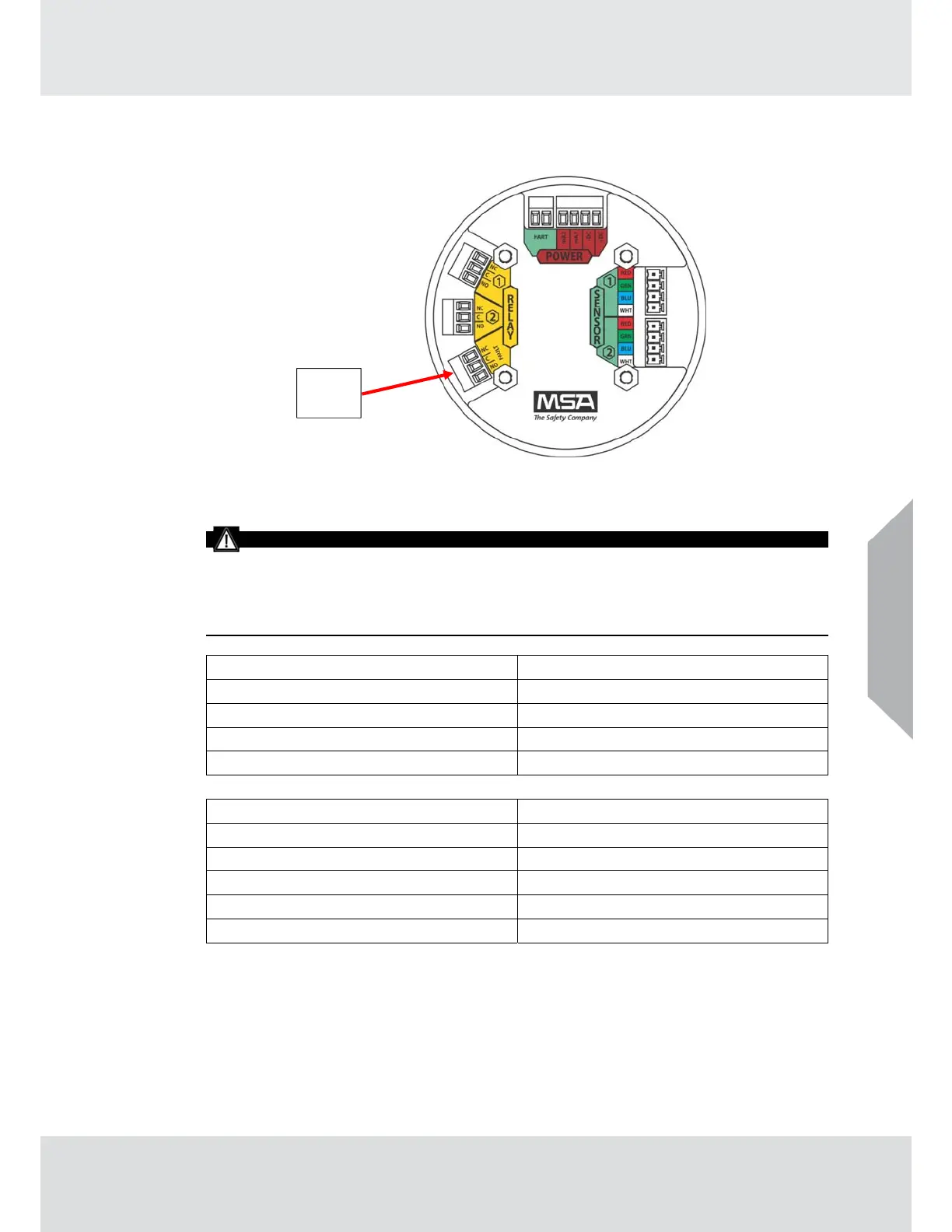
Fig. 24 Fault Relay Located on The ULTIMA X5000 Board Stack
Relay Specifications
WARNING!
The TG5000 default relay mapping mode is Common mode and must not be changed.
Changing the relay mapping will cause the TG5000 relay pack, horn, horn silence button
and installed light stack to not work properly and users may not be alerted to presence of gas.
Failure to follow the above warning can result in serious personal injury or loss of life.
ULTIMA X5000 Relay SPDT (Single Pole Double Throw)
Fault Normall
Ener
ized
Relay Rating
125 or 250 VAC
Resistive
5
30 VDC (Resistive) 5A
TG5000 Rela
Pack DPDT
Double Pole Double Throw
Low Alarm, Rela
3 Normall
De-Ener
ized
Hi
h Alarm, Rela
4 Normall
De-Ener
ized
Rela
Ratin
250 VAC
Resistive
6
30 VDC
Resistive
1.5
Tab. 8 Relay Specifications
US
US
Fault
Relay