17
Installation
3.3.4 Connecting Sensor to Transmitter Housing or Remote Junction Box
Sensors are not shipped attached to the XP junction box. All sensor modules interface with the
transmitter via a digital four-terminal connection. Up to two sensors can be connected to a single
transmitter, with each sensor getting a dedicated analog (4-20 mA) output. Consider the sensor
dimensions when choosing a mounting location for the transmitter or junction box.
To connect the sensor:
1. Remove the enclosure cover or turn the junction box lid counterclockwise to remove.
2. Pull on the metal bail to remove the board stack and expose wiring connections.
3. Route the cable from the sensor through a conduit entry hole in the enclosure.
(Repeat to attach a second sensor to the TG5000 transmitter).
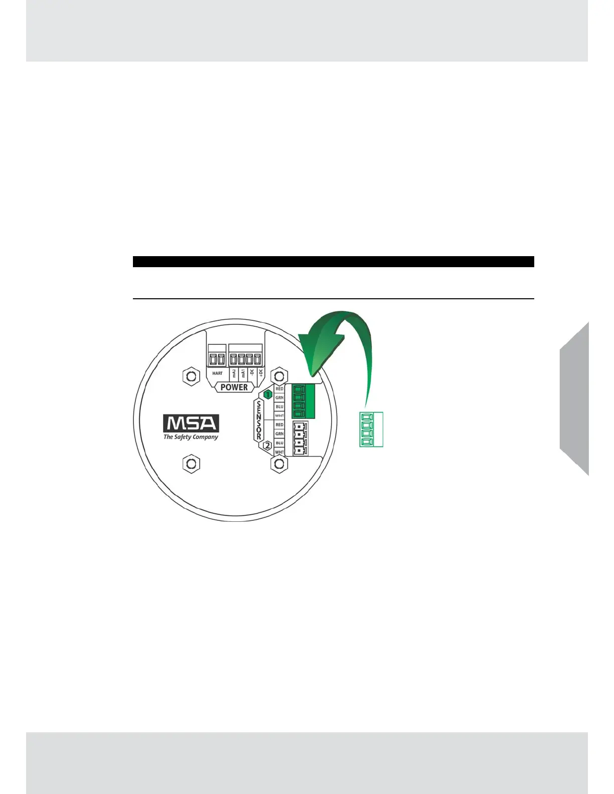
4. Connect the sensor to the "Sensor 1" position on the electronics assembly (see Fig. 9).
5. If using a second sensor, connect it to the “Sensor 2” position.
NOTICE
If only using one sensor, and it is connected to “Sensor 2” position, the TG5000 will enter
Sensor Missing fault. See Disable Sensor in section 4.2.2 for details on how to clear this fault.
Fig. 9 Connecting Sensor to the Stack
Note: Sensor connectors come pre-wired on the sensor body.
US