26
Installation
3.4.3 Instructions for Power and Analog Output
WARNING!
Read all electrical warnings and wiring requirements before connecting power to the
TG5000.
Failure to follow the above warning can result in serious personal injury or loss of life.
The TG5000 comes wired with AC for the power supply option or wired to terminal blocks (TB1)
for the non-power supply option.
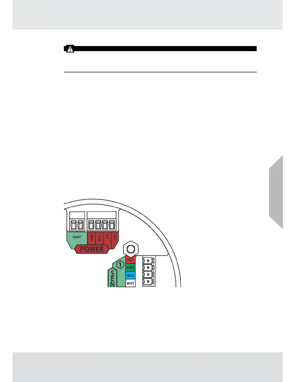
The red colored (4-pin) connector interfaces power and analog outputs 1 and 2. The HART inter-
face is a separate, green colored (2-pin) connector.
The green colored (4-pin) connectors interface sensors one and two.
Using shielded cable is recommended. The cable shield should be terminated internal to the
instrument enclosure.
TG5000 with power supply option analog output connections.
(1) Remove the TG5000 enclosure cover.
(2) Pull on the metal bail, removing electronics, to expose sensor and power connections.
(3) Remove the red colored power connector.
(4) Use a small, flat head screwdriver to open the analog wire entries on the connector.
(5) Connect the analog output wires. Wire locations are marked on the cover plate
(see Fig. 20A):
a. +DC
b.
-DC
c.
mA1 - analog output of sensor 1
d.
mA2 - analog output of sensor 2
Fig. 20A Analog, HART, and Sensor Inputs
US