• For XE and XIR Gas Monitors
locate the identifying label on the side of the plastic
shroud for the main pc board:
• A-ULTX-PCB-E-B is a two-wire unit
• A-ULTX-PCB-E-E is a three-wire unit
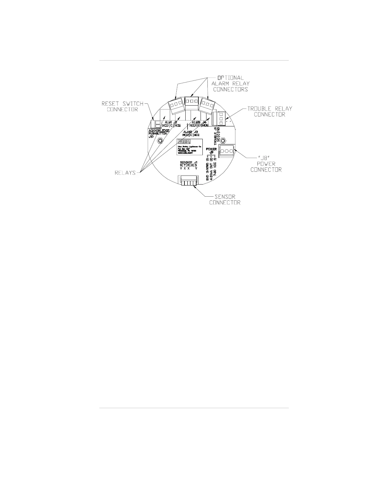
2. Connect 7 to 30 VDC power lead to J8-1 (see FIGURE 1-9).
3. Connect J8-2 to 4 to 20 mA input on remote system.
4. For three-wire operation, connect the signal ground to J8-3
(for two-wire operation, there is no connection to J8-3).
5. Connect the sensor module to labeled connector J-1 on the
main pc board.
6. Wire for optional relays and/or acknowledge push-button
(see Appendix A).
7. Assemble lid on enclosure.
Figure 1-9.
Circuit Board
Chapter 1, Installation
1-9

 Loading...


