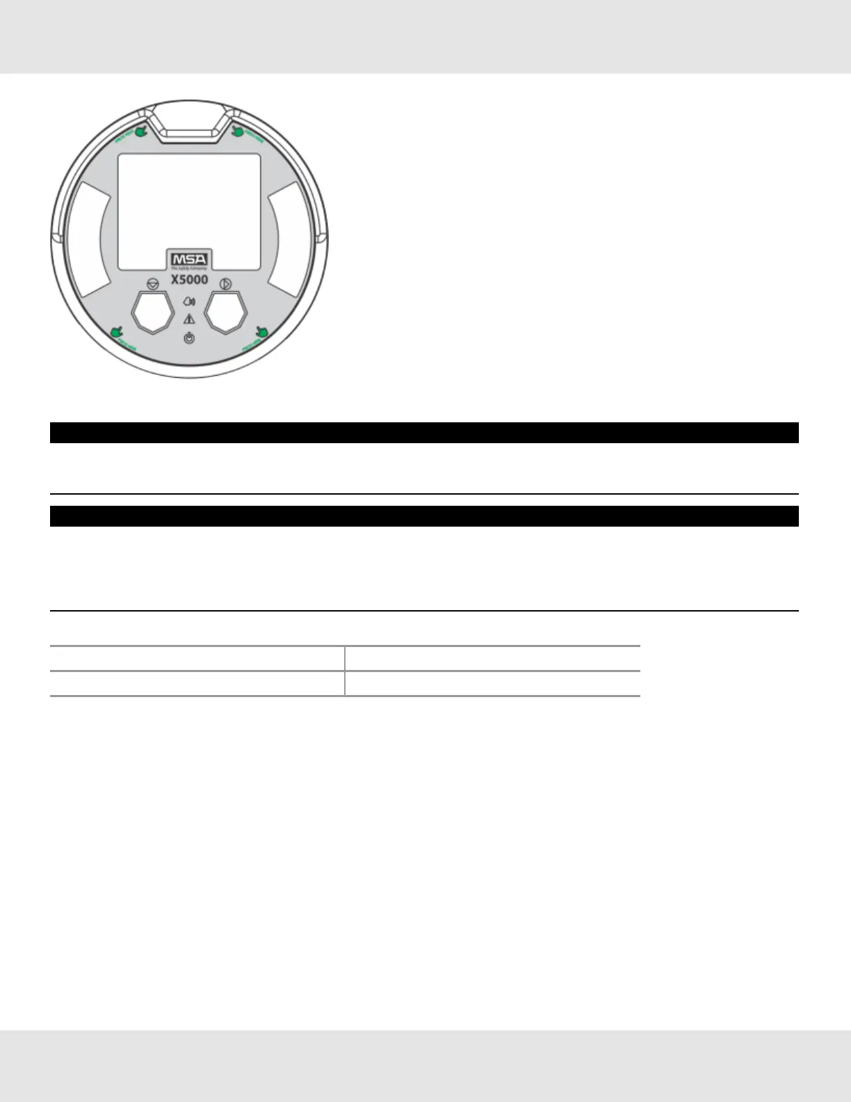
Figure 33 Highlighted areas show where to press when replacing a board stack
NOTICE
Ensurethattheelectronicsassemblyisfullyengagedinthemountingholes.Ifnotfullyseated,thetouchinterface
performancecanbenegativelyaffected
NOTICE
• AvoidpressingontheleftandrightareaswheretheLEDsarelocated.Pressingdirectlyonthedisplaywilldamagethe
displayandwillvoidthewarranty.
• CaremustbetakentoinsuretheX5000insideglasssurfaceisfreeofsmudges/dirtandgrease.Dirtandgreasecan
interferewiththetouchinterfaceofthedisplay.
Table 7 ULTIMA X5000 Installation Outline Drawing
Model DocumentNo.
ULTIMAX5000 SK3015-1051
3.6.6 RelayandPowerConnections
RelayBoardStackOverview
TheULTIMAX5000canbepurchasedwiththreerelays.Twooftherelayscanbeconfiguredforeitherde-energized
(default)orenergizedandlatchingornon-latching(default).Thethirdrelayisadedicatedfaultrelay.
AllelectricalconnectionstointernalrelayscanbemadedirectlyonthePCboard.TheboardislabeledforNormallyOpen
(NO)andNormallyClosed(NC)de-energizedstate.
US Ultima X5000 Gas Monitor 32
3 Installation