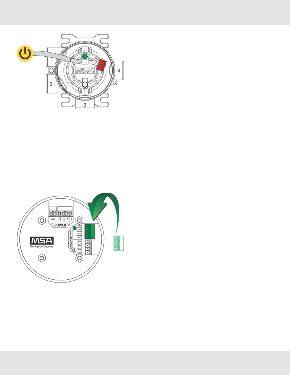
Figure 31 Connecting Power and Grounding Cable
9. Attachtheconnectortotheboardstack,makingsuretheappropriatewiresareinthecorrectterminals.
10.ConnectHARTwires(foroptionallocalHARTport).
11.ConnectanXCellorXIRPLUSsensorusingthegreenconnector.Sensorwiresarealreadyconnectedasshownon
thecoverplate(seeFigure31):
a. +DC(RED)
b. RS485Com+(GRN)
c. RS485Com-(BLU)
d. -DC(WHT)
Figure 32 Connecting a Sensor to the Board
NOTE:Sensorconnectorscomepre-wiredonthesensorbody.
NOTE:Leavingexposedwirefromtheconnectorcanelectricallyshortthesystem.
12.ReplacetheboardstackbyaligningthefourmetalstandoffswiththefourholesinsidetheULTIMAX5000housing.
Pushfirmlyontheboardstackwhereindicated(seeFigure32).
31 Ultima X5000 Gas Monitor US
3 Installation