3.6.5 InstructionsforPowerandAnalogOutput
WARNING!
ReadallelectricalwarningsandwiringrequirementsbeforeconnectingpowertotheULTIMAX5000.
Failuretofollowthiswarningcanresultinseriouspersonalinjuryordeath.
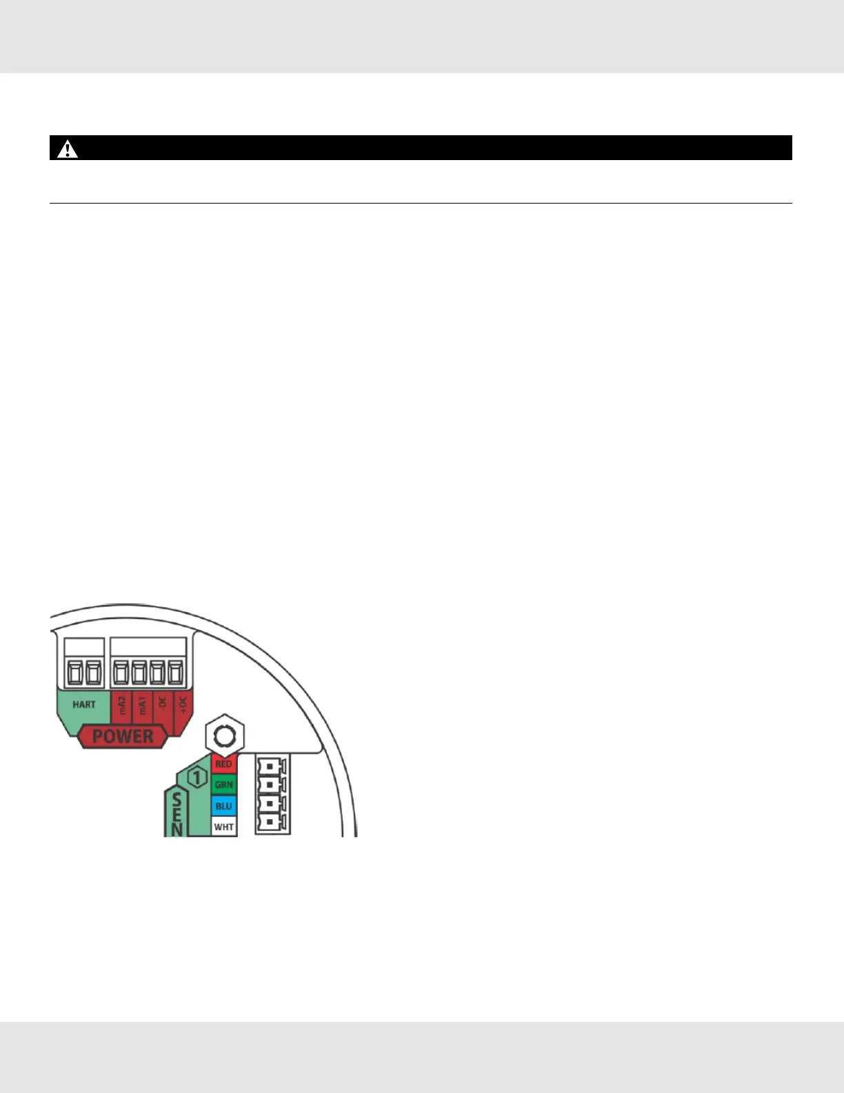
Theredcolored(4-pin)connectorinterfacespowerandanalogoutputs1and2.TheHARTinterfaceisaseparate,green
colored(2-pin)connector.
Thegreencolored(4-pin)connectorsinterfacesensorsoneandtwo.
Usingshieldedcableisrecommended.Thecableshieldshouldbeterminatedinternaltotheinstrumentenclosureusingthe
crimpterminalprovided(seeFigure30).
1. RemovetheULTIMAX5000coverbyturningcounter-clockwise.
2. Pullonthemetalbail,removingelectronics,toexposesensorandpowerconnections.
3. Removetheredcoloredpowerconnector.
4. Useasmall,flatheadscrewdrivertoopenwireentriesontheconnector.
5. Stripcablejackettoexposeshieldandthefourindividualwires.
6. Connectthepowerandanalogoutputwires.Wirelocationsaremarkedonthecoverplate(seeFigure29):
a. +DC
b. -DC
c. mA1-analog output of sensor 1
d. mA2-analog output of sensor 2
Figure 30 Power, HART, and Sensor Inputs
7. Tightenscrewsonconnectorandtuggentlyonwirestoensuretheyaresecure.
8. Connectshieldofcabletobaseofinstrumenthousing(seeFigure30).
US Ultima X5000 Gas Monitor 30
3 Installation