Medium Frame 2 & 3 Stage Snow Throwers
136
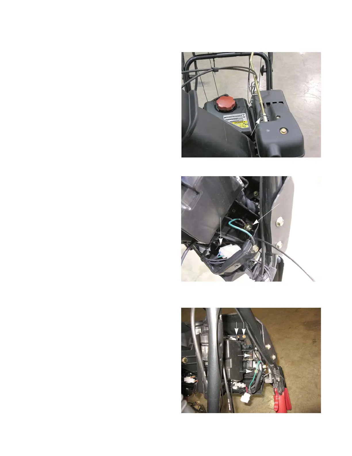
Chute Control Assembly
To remove/replace the Chute Control Assembly:
1. Remove the hair pin clip that secures the shaft to
the Remote Head.
NOTE: The shaft has an offset so that it can be
used to manually rotate the chute.
2. Slide the shaft forward until it clears the Chute Con-
trol Assembly’s Coupler. See Figure 11.45.
3. Remove the shaft.
4. Disconnect Pitch Control Cables from the Chute
Deflector by following the procedures described in
the appropriate Remote Pitch Control Head section
of this chapter.
5. Disconnect the Chute Control Motor Connectors.
See Figure 11.46.
NOTE: Folding the handle bars down will allow eas-
ier access to the control assembly.
NOTE: One of the connectors is not visible in Figure
11.46.
6. Disconnect the ground lead from the control assem-
bly, using a 1/2” wrench.
NOTE: The ground lead is used to drain away any
static electricity that may build up on the
chute. It does not supply a ground for the
Chute Control Motors.
7. Remove the six screws that hold the assembly in
the dash panel, using a 3/8” wrench.
8. Lift the assembly out of the snow thrower.
9. Install the Chute Control Assembly by following the
previous steps in reverse order.
10. Test run the unit in a safe area before returning it to
service.
Figure 11.45
Hair Pin Clip
Figure 11.46
Motor Connector
Ground Lead
 Loading...